Gas discharge tube (gdt) products, Cg/cg2 series, Surface mount (ms) dimensions – Littelfuse CG_CG2 SN Series User Manual
Page 3: Device dimensions, Shaped lead
Gas Discharge Tube (GDT) Products
©2013 Littelfuse, Inc.
Revised: January 10, 2013
Specifications are subject to change without notice.
Please refer to www.littelfuse.com for current information.
Customer should verify actual device performance in their specific applications.
CG/CG2 Series
CG/CG2 Series
Device Dimensions
[0.331 ± 0.012]
8.4 ± 0.3
[0.239 ± 0.012]
6.07 ± 0.3
[0.0157 ± 0.0012]
0.40 ± 0.03
0.004
2 Surfaces
[0.032]
0.80
[0.388 ± 0.012]
9.85 ± 0.30
[0.439 ± 0.012]
11.15 ± 0.30
[0.331 ± 0.012]
8.40 ± 0.3
8.10 Max.
[0.319 DIA Max.]
9.85
[0.388]
11.65
[0.459]
8.60
[0.339]
1.80
[0.071]
TOP VIEW
PROFILE VIEW
SOLDER PAD LAYOUT
6.05 ± 0.2
[0.238 ± 0.0079]
5.58 [0.220]
ø8.30±0.1
R5.29 [R0.208]
4 ± 0.2
[0.157 ± 0.0079]
8.30 ± 0.1
[0.327 ± 0.0039]
8.71 [0.343]
2.29 [0.090]
5.89 [0.232]
0.47 ± 0.1
[0.019 ± 0.0039]
9.30 ± 0.2
[0.366 ± 0.0079]
TOP VIEW
PROFILE VIEW
SEMI–PROFILE VIEW
SOLDER PAD LAYOUT
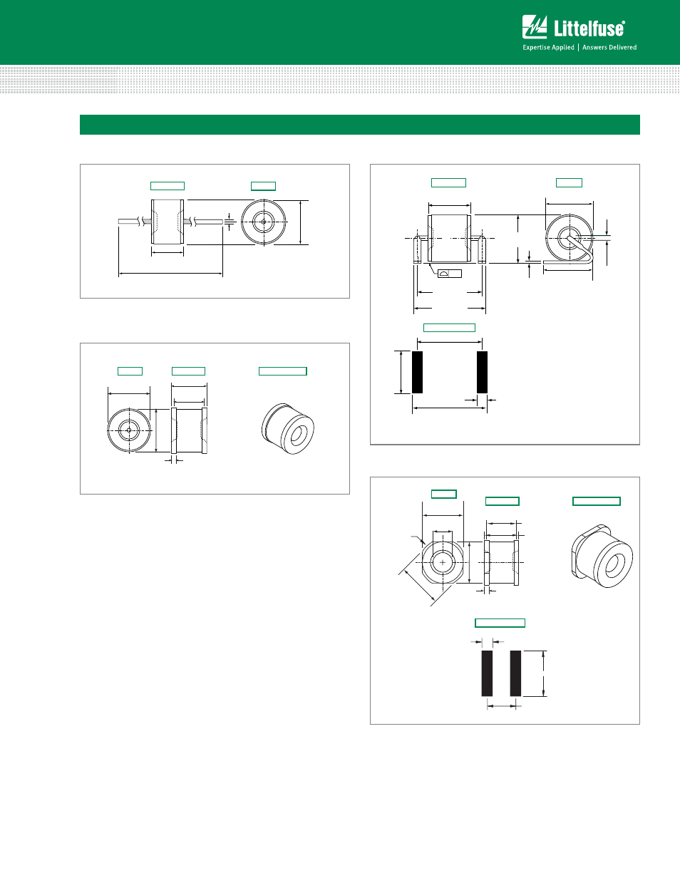
Leaded 'LS' Type Shaped Lead Devices
'MS' Type Devices
Leaded 'L' Type Straight Axial Devices
Core Devices
6.05 ± 0.2
[0.268 ± 0.0080]
5.58 [0.232]
8.71 [0.343]
2.29 [0.090]
5.89 [0.232]
4.00
16.00
24.00
11.50
1.75
TOP VIEW
PROFILE VIEW
SEMI–PROFILE VIEW
SOLDER PAD LAYOUT
TOP VIEW
PROFILE VIEW
SOLDER PAD LAYOUT
DIMENSIONS
mm
[inches]
Shaped Lead
0.512 (13.0) Arbor
Hole Dia.
1.01
(25.7)
12.99
(330.0)
Direction of Feed
16
250G
XXXX
Voltage Rating
Current Rating
Date Code
(Contact Littelfuse
for additional
information)
Littelfuse
Trademark
8.30 ± 0.1
9.30 ± 0.2
ш8.30±0.1
Ш6.81 [0.268]
0.47 ± 0.1
R5.29 [R0.208]
4 ± 0.2
[0.161 ± 0.0080]
8.10
DIA. MAX.
[0.319]
6.07 ± 0.15
0.81
DIA. TYP.
[0.032]
62 ± 2
[0.239 ± 0.006]
[0.331 ± 0.012]
8.4 ± 0.3
[0.0157 ± 0.0012]
0.40 ± 0.03
0.004
2 Surfaces
[0.032]
0.81
[0.388 ± 0.012]
9.85 ± 0.30
[0.439 ± 0.012]
11.15 ± 0.30
[0.239 0.012]
6.07 0.30
±
±
[0.331 ± 0.012]
8.40 ± 0.3
9.85 [0.388]
11.68 [0.460]
8.66 [0.341]
1.77 [0.070]
8.10 Max.
[0.319 DIA Max.]
16
250G
XXXX
16
250G
XXXX
16
250G
XXXX
16
250G
XXXX
16
250G
XXXX
Surface Mount (MS) Dimensions
TOP VIEW
PROFILE VIEW
6.07 ± 0.15
[0.239 ± 0.0059]
5.89 [0.232]
8.10 Max.
[0.032 Max.]
8.1
0 Max
.
TOP VIEW
PROFILE VIEW
SEMI–PROFILE VIEW
0.47 ± 0.1
[0.019 ± 0.0039]