Transient voltage suppression diodes, Da a c b – Littelfuse 1.5KE Series User Manual
Page 5
Transient Voltage Suppression Diodes
© 2014 Littelfuse, Inc.
Specifications are subject to change without notice.
Revised: 01/24/14
Axial Leaded – 1500W > 1.5KE series
Physical Specifications
Weight
0.045oz., 1.2g
Case
JEDEC DO-201 molded plastic body over
passivated junction.
Polarity
Color band denotes the cathode except
Bipolar.
Terminal
Matte Tin axial leads, solderable per
JESD22-B102.
Dimensions
Dimensions
Inches
Millimeters
Min
Max
Min
Max
A
1.000
-
25.40
-
B
0.285
0.375
7.20
9.50
C
0.038
0.042
0.96
1.07
D
0.190
0.210
4.80
5.30
D
A
A
C
B
Cathode Band
(for Uni-directional products only)
DO-201
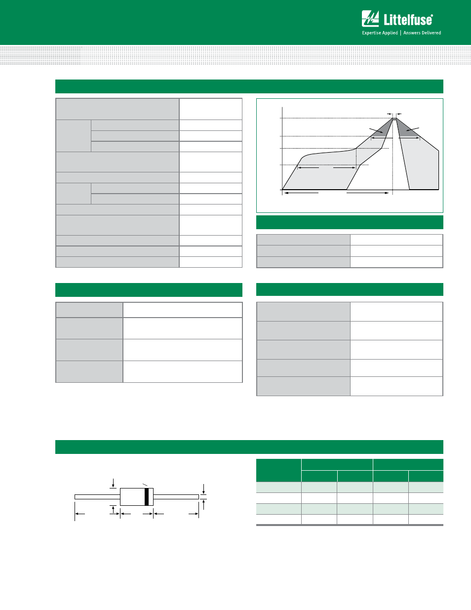
Soldering Parameters
Te
mperature (T
)
Time (t)
T
s(min)
T
s(max)
T
L
T
P
t
s
Preheat
t
L
t
p
Ramp-up
Critical Zone
T
L
to T
P
Ramp-down
t 25˚C to Peak
25˚C
Reflow Condition
Lead–free assembly
Pre Heat
- Temperature Min (T
s(min)
)
150°C
- Temperature Max (T
s(max)
)
200°C
- Time (min to max) (t
s
)
60 – 180 secs
Average ramp up rate (Liquidus Temp
(T
L
) to peak
3°C/second max
T
S(max)
to T
L
- Ramp-up Rate
3°C/second max
Reflow
- Temperature (T
L
) (Liquidus)
217°C
- Time (min to max) (t
s
)
60 – 150 seconds
Peak Temperature (T
P
)
260
+0/-5
°C
Time within 5°C of actual peak
Temperature (t
p
)
20 – 40 seconds
Ramp-down Rate
6°C/second max
Time 25°C to peak Temperature (T
P
)
8 minutes Max.
Do not exceed
280°C
Flow/Wave Soldering (Solder Dipping)
Peak Temperature :
265
O
C
Dipping Time :
10 seconds
Soldering :
1 time
Environmental Specifications
High Temp. Storage
JESD22-A103
HTRB
JESD22-A108
Temperature Cycling
JESD22-A104
H3TRB
JESD22-A101
RSH
JESD22-B106