Teccor, Brand thyristors, 55 amp standard scrs – Littelfuse Sxx55x Series User Manual
Page 4
324
Revised: 09/23/13
©2013 Littelfuse, Inc
Specifications are subject to change without notice.
Teccor
®
brand Thyristors
55 Amp Standard SCRs
Sxx55x Series
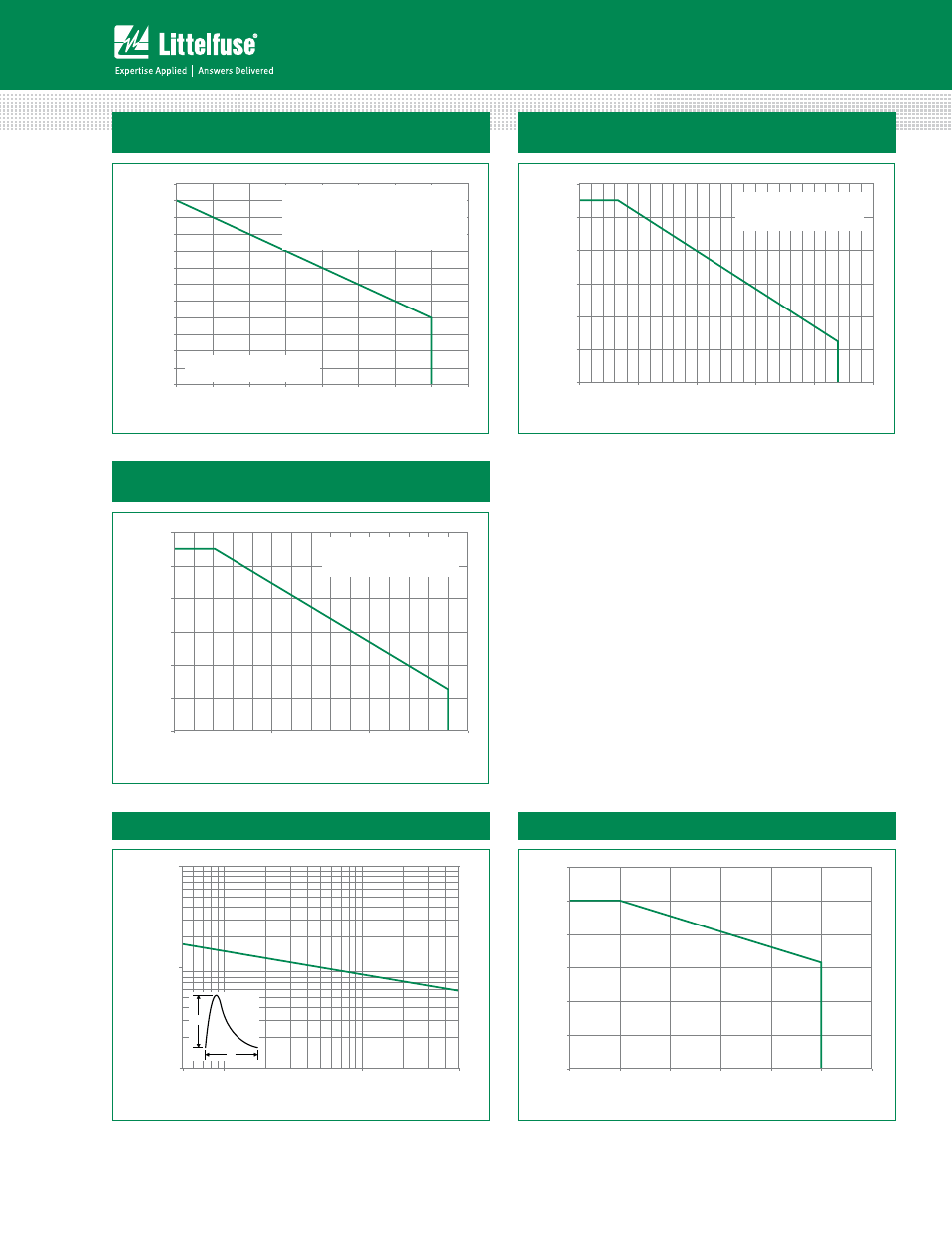
Figure 7: Maximum Allowable Case Temperature
vs. Average On-State Current
Figure 8: Maximum Allowable Ambient Temperature
vs. RMS On-State Current
Figure 9: Maximum Allowable Ambient Temperature
vs. Average On-State Current
70
75
80
85
90
95
100
105
110
115
120
125
130
0
5
10
15
20
25
30
35
40
Average On-State Current [I
T(AVE)
] - Amps
Maximum Allo
w
able
Case
Temper
at
ur
e
(T
C
) - °C
CURRENT WAVEFORM: Sinusoidal
LOAD: Resistive or Inductive
CONDUCTION ANGLE: 180°
The "R" or "M" package rating is intended for high
surge condition use only and not recommended
for >32A (AV) continuous current use since narrow
pin leads depending on lead length can exceed
PCB solder melting temperature. "W" package is
recommended for >32A (AV) continuous current
requirements.
0
20
40
60
80
100
120
0.0
0.5
1.0
1.5
2.0
2.5
RMS On-State Current [I
T(RMS)
] - Amps
Maximum Allo
w
a
ble Ambient
Temper
at
ur
e (T
A
) - °C
CURRENT WAVEFORM: Sinusoidal
LOAD: Resistive or Inductive
CONDUCTION ANGLE: 180°
FREE AIR RATING
0
20
40
60
80
100
120
0.0
0.5
1.0
1.5
Average On-State Current [I
T(AVE)
] - Amps
Maximum Allo
w
able Ambient
Temper
at
ur
e
(T
A
) - °C
CURRENT WAVEFORM: Sinusoidal
LOAD: Resistive or Inductive
CONDUCTION ANGLE: 180°
FREE AIR RATING
Figure 10: Peak Capacitor Discharge Current
Figure 11: Peak Capacitor Discharge Current Derating
100
1000
10000
0.5
1.0
10.0
50.0
P
eak Disc
har
g
e
Cur
rent (I
TM
) -
Amps
Pulse Current Duration (t
w
) - ms
I
TRM
t
W
0.0
0.2
0.4
0.6
0.8
1.0
1.2
0
25
50
75
100
125
150
Nor
m
aliz
ed P
eak Cur
re
nt
Case Temperature (T
C
) - °C
Note: xx = voltage