Littelfuse SE-135 Series User Manual
Protection relays & controls, Ground-fault ground-check monitor description, Specifications
Protection Relays & Controls
© 2013 Littelfuse Protection Relays & Controls
Rev: 4-A-061913
SE-134C Based on Manual Rev 7-A-050613
SE-135 Based on Manual Rev 3-A-051413
Littelfuse.com/se-134c, Littelfuse.com/se-135
Trailing Cable Protection–Ground-Fault Ground-Check Monitoring
SE-134C, SE-135 SEriES (PGM-8134)
Ground-Fault Ground-Check Monitor
Description
The SE-134C/SE-135 is a microprocessor-based, combination
ground-wire monitor and ground-fault relay for resistance-
grounded or solidly grounded systems. It continuously monitors
the integrity of the ground conductor to protect portable
equipment from hazardous voltages caused by ground faults.
The SE-134C/SE-135 is field proven in monitoring trailing cables
on large mobile equipment such as drag-lines, mining shovels,
shore-to-ship power cables, dock-side cranes, stacker-reclaimers,
submersible pumps, and portable conveyors.
Specifications
IEEE Device Numbers
Checking or Interlocking Relay (3GC),
Ground fault (50G/N, 51G/N)
Input Voltage
65-265 Vac; 85-275 Vdc; 18-72 Vdc
Dimensions
H 213 mm (8.4"); W 99 mm (3.9"); D 132 mm (5.2");
Trip Level Settings
0.5-12.5 A for SE-CS10, 2 - 50 A for SE-CS40
Trip Time Settings
0.1-2.5 s
Contact Operating Mode
Selectable fail-safe or non-fail-safe
Harmonic Filtering
Standard feature
Test Button
Standard feature
Reset Button
Standard feature
Output Contacts
Isolated Form A and Form B, Two Form C
Approvals
CSA certified, UL Listed (E340889),
C-Tick (Australia), CE
Conformally Coated
Standard feature
Warranty
5 years
Mounting
Panel, Surface
GC Trip Resistance
28Ω (Standard), 45Ω (XGC Option)
OrdErinG
nuMbEr
OPTiOn
POwEr
SuPPly
COMM
SE-134C
Blank or
XGC
0=120/240
Vac/Vdc
0=None
1=24/48 Vdc
SE-135
Blank or
XGC
0=120/240
Vac/Vdc
0=None
1=24/48 Vdc
3=
Ethernet
Ordering Information
See Current Transformer Selection Guide and Accessory Information.
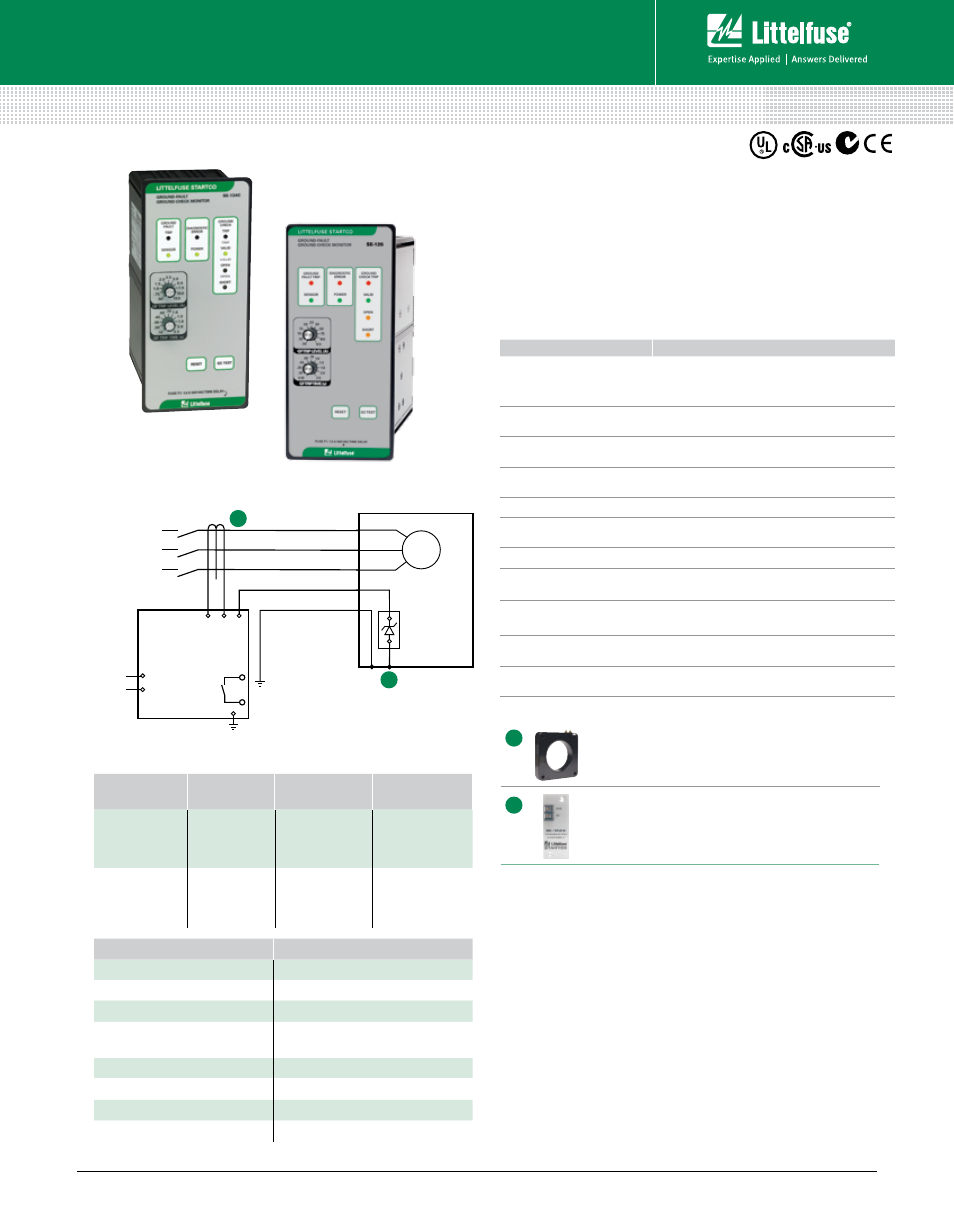
Simplified Circuit Diagram
SE-CS10 or SE-CS40 Series Ground-Fault
Current Transformer
Required zero-sequence current transformer
detects ground-fault current.
SE-TA6A Series, SE-TA12A Series
Termination Assembly
Required termination assembly; temperature
compensated.
Accessories
A
B
FEaTurES
bEnEFiTS
Adjustable pickup
(0.5 - 12.5 A for SE-CS10)
(2 - 50 A for SE-CS40)
Unit can be used on a wide variety of trailing cable
applications
Adjustable time delay
(0.1 - 2.5 s)
Adjustable trip delay for quick protection and system
coordination
Output contacts
Separate annunciation of ground-fault and ground-
check faults
Ground-check
LED indication
Indication of open or short ground-check wire
makes it easier to find faults
CT-loop monitoring
Alarms when CT is not connected
High-induced-ac
rejection
Makes unit suitable for applications with high
voltages and long cables
DFT (Harmonic) filter
Prevents false operation
Zener-characteristic
termination assembly
Provides reliable ground-check loop verification
Fail-safe circuits
Ensures ground-check and ground-fault circuits
remain safe even in the event of equipment failure
Conformal coating
Additional coating protects circuit boards against
harsh environment
xGC option
Increases maximum cable length for ground-check
monitoring (10 km typical)
Features & Benefits
aCCESSOriES
rEquirEMEnT
SE-CS10 Series
Required
SE-CS40 Series (for SE-135)
Optional
SE-TA6A Series (for SE-134C)
Required
SE-TA12A/SE-TA12B
Combination (for SE-134C)
Optional
SE-TA12A Series (for SE-135)
Required
SE-IP65CVR-G
Optional
RK-132
Optional
PPI-600V
Optional
TRAILING
CABLE
CT
L2
L1
TERMINATION
DEVICE
A
G
GC
C
B
GROUNDED
SUPPLY
M
SE-134C SERIES
SE-135 SERIES
(Ground-Fault
Ground-Check
Monitor)
B
A