Surface mount fuses, Ceramic fuse > 440 series, Average time current curves – Littelfuse 440 Series User Manual
Page 2: Soldering parameters temperature derating curve
© 2013 Littelfuse, Inc.
Specifications are subject to change without notice.
Revised: 12/19/13
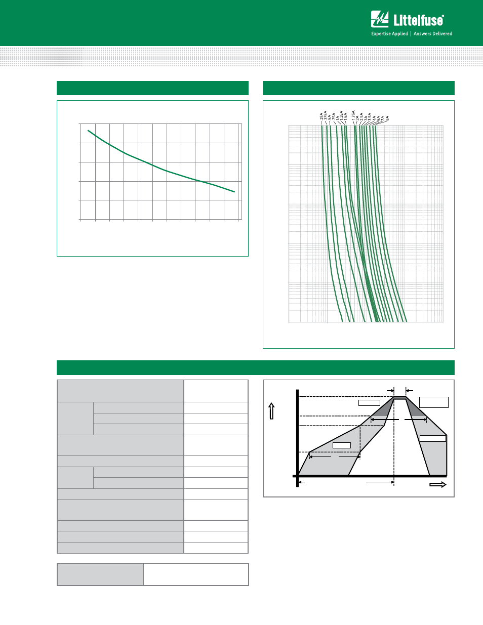
Surface Mount Fuses
Ceramic Fuse > 440 Series
Average Time Current Curves
0.001
0.1
1.0
10.0
100.0
1000.
0.01
0.1
1
10
100
TIME IN SECONDS
CURRENT IN AMPERES
Reflow Condition
Pb-free assembly
pre Heat
- Temperature min (T
s(min)
)
150°C
- Temperature max (T
s(max)
)
200°C
- Time (min to max) (t
s
)
60 – 180 seconds
Average Ramp-up Rate (liquidus Temp
(T
l
) to peak)
3°C/second max.
T
S(max)
to T
l
- Ramp-up Rate
5°C/second max.
Reflow
- Temperature (T
l
) (liquidus)
217°C
- Temperature (t
l
)
60 – 150 seconds
peak Temperature (T
p
)
260
+0/-5
°C
Time within 5°C of actual peak
Temperature (t
p
)
10 – 30 seconds
Ramp-down Rate
6°C/second max.
Time 25°C to peak Temperature (T
p
)
8 minutes max.
Do not exceed
260°C
Soldering Parameters
Temperature Derating Curve
40
60
80
100
120
140
-65 -45 -25 -5 15 35 55 75 95 115 135 155
TEMPERATURE (°C)
PE
RC
EN
T
OF
RA
TI
NG
Time
Te
mperatur
e
T
P
T
L
T
S(max)
T
S(min)
25
t
P
t
L
t
S
time to peak temperature
(t 25ºC to peak)
Ramp-down
Ramp-up
Preheat
Critical Zone
T
L
to T
P
Example:
For continuous operation at 75 degrees celsius, the fuse should be derated as follows:
I = (0.80)(0.85)I
RAT
= (0.68)I
RAT
Note:
1. Derating depicted in this curve is in addition to the standard derating of 20% for
continuous operation.
Wave Soldering
260°C, 10 seconds max.