Teccor, Brand thyristors – Littelfuse Dxx25L Series User Manual
Page 4
382
Revised: 09/23/13
©2013 Littelfuse, Inc
Specifications are subject to change without notice.
Teccor
®
brand Thyristors
15 / 20 / 25 Amp Rectifiers
Dxx15L & Dxx20L & Dxx25L Series
Environmental Specifications
Test
Specifications and Conditions
High Temperature
Voltage Blocking
MIL-STD-750: Method 1040, Condition A
Rated V
RRM
, 125°C, 1008 hours
Temperature Cycling
MIL-STD-750: Method 1051
-40°C to 150°C, 15-minute dwell,
100 cycles
Biased Temperature &
Humidity
EIA/JEDEC: JESD22-A101
320VDC, 85°C, 85%RH, 1008 hours
High Temp Storage
MIL-STD-750: Method 1031
150°C, 1008 hours
Low-Temp Storage
1008 hours; -40°C
Thermal Shock
MIL-STD-750: Method 1056
0°C to 100°C, 5-minute dwell,
10-second transfer, 10 cycles
Autoclave
(Pressure Cooker Test)
EIA/JEDEC: JESD22-A102
121°C, 100%RH, 2atm, 168 hours
Resistance to
Solder Heat
MIL-STD-750: Method 2031
260°C, 10 seconds
Solderability
ANSI/J-STD-002, Category 3, Test A
Lead Bend
MIL-STD-750: Method 2036, Condition E
Physical Specifications
Terminal Finish
100% Matte Tin Plated
Body Material
UL recognized epoxy meeting flammability
classification 94V-0
Lead Material
Copper Alloy
Design Considerations
Careful selection of the correct device for the application’s
operating parameters and environment will go a long way
toward extending the operating life of the rectifier. Good
design practice should limit the maximum continuous
current through the main terminals to 75% of the device
rating. Other ways to ensure long life for a power discrete
semiconductor are proper heat sinking and selection of
voltage ratings for worst case conditions. Overheating,
overvoltage (including dv/dt), and surge currents are
the main killers of semiconductors. Correct mounting,
soldering, and forming of the leads also help protect
against component damage.
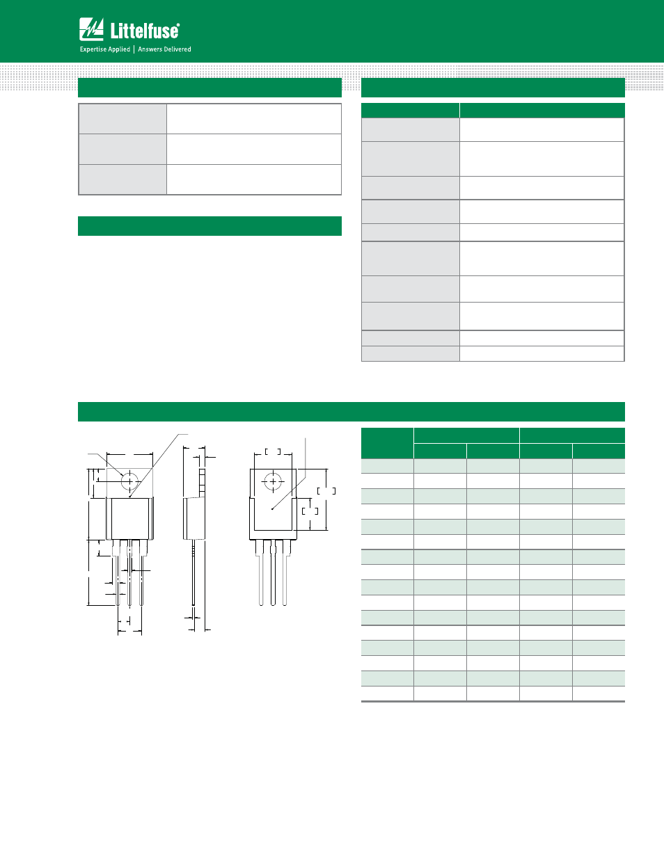
Dimensions — TO-220AB (L-Package) — Isolated Mounting Tab
Dimension
Inches
Millimeters
Min
Max
Min
Max
A
0.380
0.420
9.65
10.67
B
0.105
0.115
2.67
2.92
C
0.230
0.250
5.84
6.35
D
0.590
0.620
14.99
15.75
E
0.142
0.147
3.61
3.73
F
0.110
0.130
2.79
3.30
G
0.540
0.575
13.72
14.61
H
0.025
0.035
0.64
0.89
J
0.195
0.205
4.95
5.21
K
0.095
0.105
2.41
2.67
L
0.060
0.075
1.52
1.91
M
0.085
0.095
2.16
2.41
N
0.018
0.024
0.46
0.61
O
0.178
0.188
4.52
4.78
P
0.045
0.060
1.14
1.52
R
0.038
0.048
0.97
1.22
A
H
G
B
F
E
C
D
L
R
T
C
MEASURING POINT
AREA (REF.) 0.17 IN
2
O
P
N
M
.320
8.13
.526
13.36
.276
7.01
K
J
Not Used
CATHODE
ANODE
Note: Maximum torque to
be applied to mounting tab
is 8 in-lbs. (0.904 Nm).