Littelfuse T2900 Series User Manual
T2900 series, Protection relays & controls, Phase differential relay description
Protection Relays & Controls
© 2013 Littelfuse Protection Relays & Controls
Littelfuse.com/t2900
Generator & Single-Function Protection–Differential
T2900 SerieS
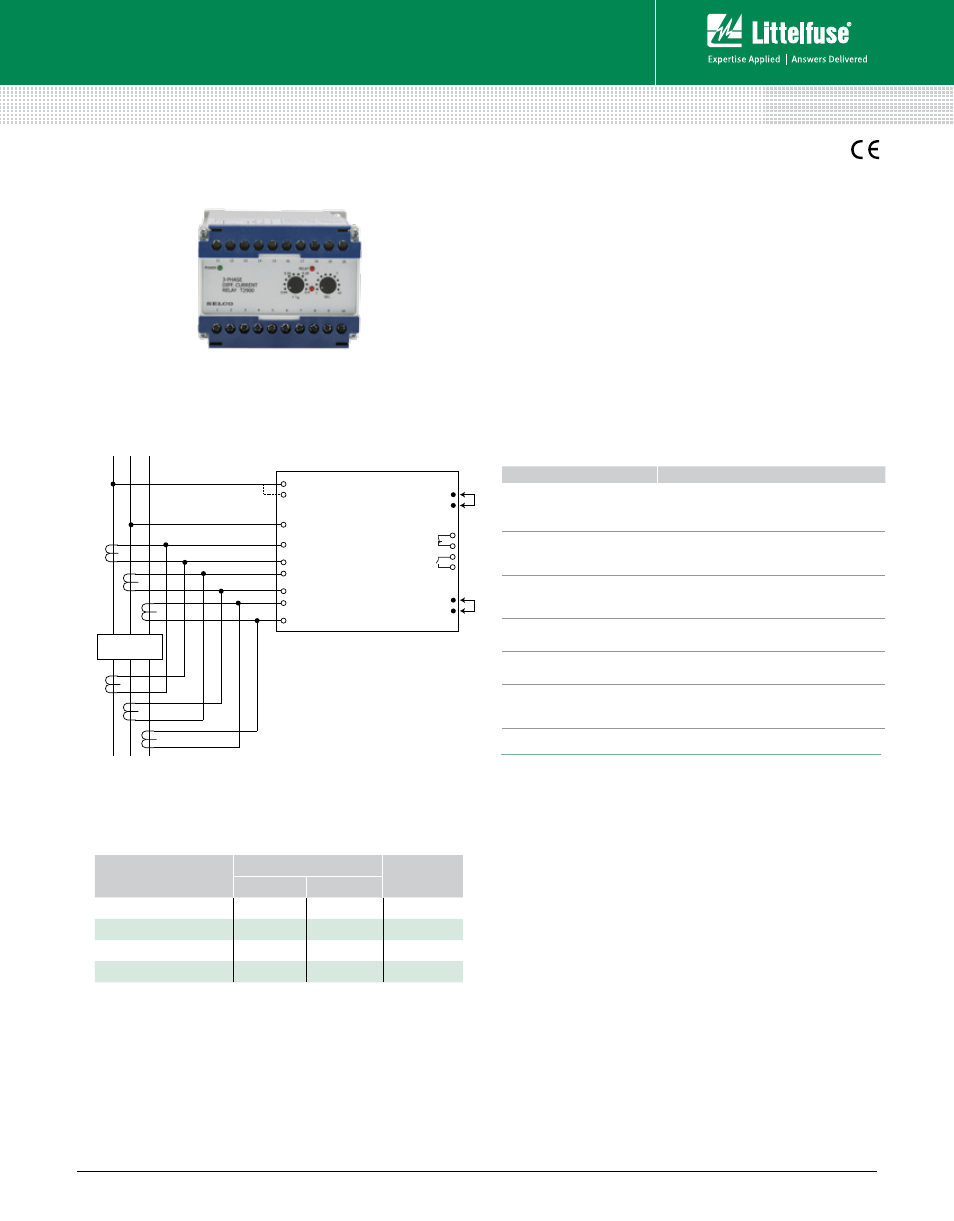
3-Phase Differential Relay
Description
The T2900 3-Phase Differential Relay is designed for
monitoring current leakage in generators. The T2900
measures the differential current of each of the 3 phases.
The differential currents are measured by connecting a
current transformer for each winding in parallel with inverse
polarity. The highest of the 3 currents is selected and,
if it exceeds the preset level (0.04-0.4 x I
N
), the pick-up
LED will indicate this and the delay timer will be started.
After the preset time has expired, the output relay and
the corresponding LED will be activated, provided that the
current level was exceeded for the entire delay time. The time
delay can be adjusted between 1-10 sec. This time delay can
be reduced by a factor 10 by bridging terminals 18 and 19.
Specifications
Trip Level
0.04-0.4 x I
N
Delay
1-10 sec. (0.1-1 sec. when bridging terminals 18 and 19)
Max. Voltage
660 V
Voltage Range
60-110%
Consumption
Voltage 5 VA at U
N
Current 0.3 VA at I
N
Continuous Current
2 x I
N
Frequency Range
45-400 Hz
Output Relay
Normally de-energized, latching, resetable
Contact Rating
AC: 400 V, 5 A, 2000 VA
DC: 150 V, 5 A, 150 W
Overall Accuracy
±5%
Repeatability
±1%
Operating Temperature –20°C to + 70°C
Dielectric Test
2500 V, 50 Hz
EMC
CE according to EN50081-1, EN50082-1, EN50081-2,
EN50082-2
Approvals
Certified by major marine classification societies
Burn-in
50 hours before final test
Enclosure Material
Polycarbonate. Flame retardant
Weight
0.5 kg
Dimensions H
70 mm (2.76”); W 100 mm (3.94”); D 115 mm (4.52”)
Installation
35 mm DIN rail or 4 mm (
3
/
16
”) screws
Ordering Information
Simplified Circuit Diagram
Standard types: I
N
= 5 A and output relay normally de-energized.
Other combinations and voltages are available on request.
Features & Benefits
OrDerinG number
TerminalS
i
n
1-3
2-3
T2900.0010
450 V
400 V
5 A
T2900.0020
230 V
5 A
T2900.0030
480 V
415 V
5 A
T2900.0040
110 V
100 V
5 A
SUPPLY
DIFFERENTIAL
CURRENT
DEVICE UNDER
PROTECTION
I
1
U
I
2
I
3
2
3
11
12
13
14
15
16
1
10
9
8
7
6
5
19
18
L
1
L
2
L
3
T2900
(3-Phase Differential Relay)
FeaTureS
beneFiTS
Accepts high supply
voltage variation
Ensures correct operation in spite of voltage
supply fluctuations (fulfills marine class
requirement)
Visual indication of power,
pick-up, and output trip
Provides quick and concise status information
Direct line-line or line-
neutral voltage supply (up
to 690 Vac)
Simplifies design and installation.
No need for PTs.
Built-in capacitor
back-up supply
Ensures correct operation in spite of drop in
the supply voltage
Galvanic isolated inputs
Protects the unit against high AC voltage and
currents from the installation including spikes
DIN-rail or screw-mount
& adjustment by
potentiometers
Easy installation
bridge between terminals 5 and 6 results in latching relay.
bridge between terminals 18 and 19 reduces time delay to 0.1-1 sec.
Rev: 4-A-050213