Sidactor, Protection thyristors, Broadband optimized – Littelfuse SDP Biased Series 5x6 QFN User Manual
Page 2: Protection, Surge ratings, 50/60hz ratings, V-i: characteristics capacitance vs. voltage, Thermal considerations
SIDACtor
®
Protection Thyristors
31
Revised: 09/26/13
© 2013 Littelfuse, Inc.
Specifications are subject to change without notice.
Broadband Optimized
™
Protection
SDP Biased Series 5x6QFN
Series
I
PP
I
TSM
2x10µs
1.2x50µs/8x20µs
10x700/5x310µs
10x1000µs
600V
RMS
1 cycle
A min
A min
A min
A min
A
RMS
C
500
400
200
100
30
Surge Ratings
Parameter Name
Test Conditions
Value
Units
I
TSM
Maximum non-reptitive
on-state current, 50/60Hz
0.5s
6.5
A
1s
4.6
2s
3.4
5s
2.3
30s
1.3
900s
0.73
50/60Hz Ratings
I
H
I
T
I
S
I
DRM
V
DRM
V
T
+V
-V
+I
-I
V
S
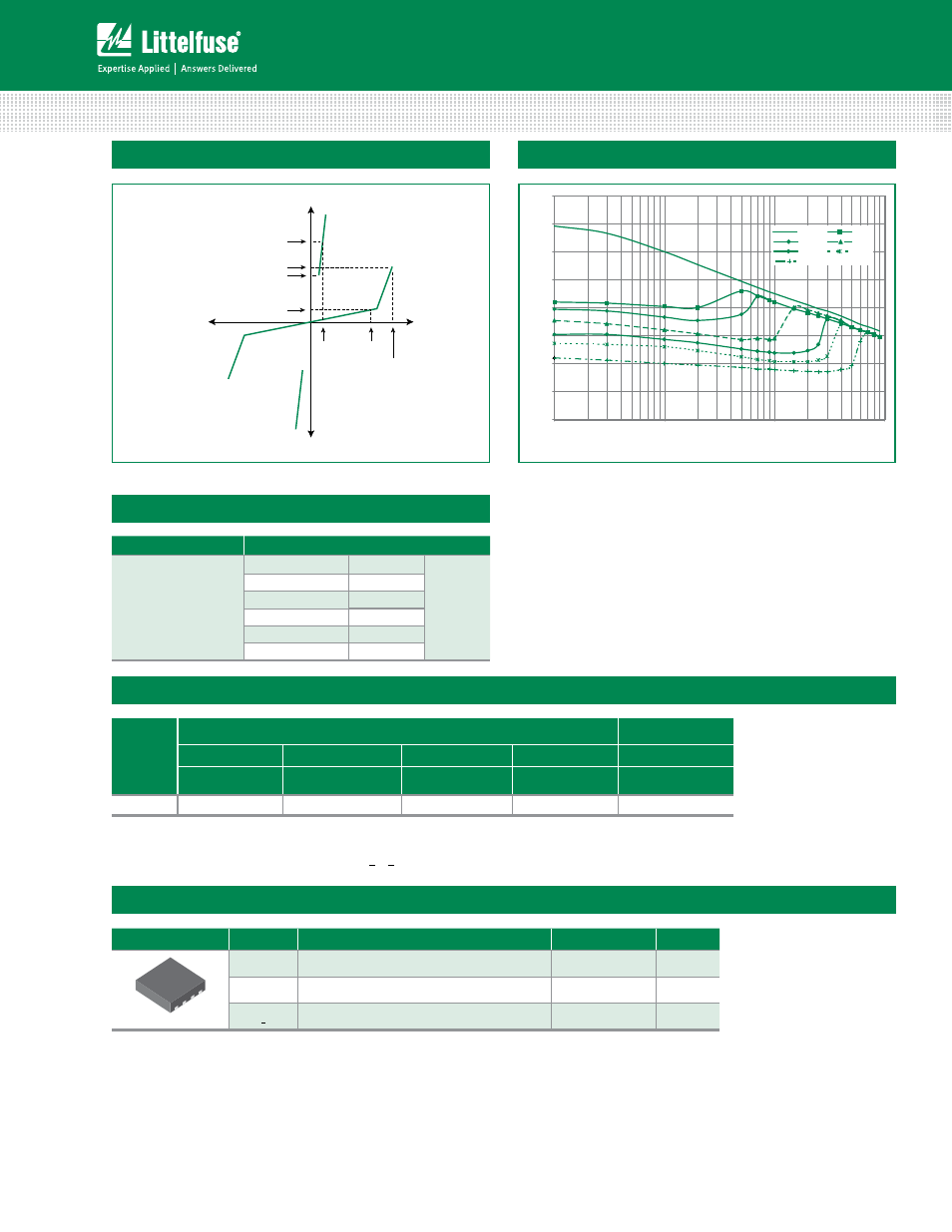
V-I: Characteristics
Capacitance vs. Voltage*
0
5
10
15
20
25
30
35
40
0
0
1
0
1
1
1
.
0
Line Voltage (V)
Capacitance (pF)
0V
3.3V
5V
12V
24V
30V
50V
Bias Voltage
* Bias voltage must be lower than V
DRM
Notes:
- Peak pulse current rating (I
PP
) is repetitive and guaranteed for the life of the product.
- I
PP
ratings applicable over temperature range of -40ºC to +85ºC
- The device must initially be in thermal equilibrium with -40°C < T
J
< +150°C
Package
Symbol
Parameter
Value
Unit
5x6 QFN
T
J
Junction Temperature
-40 to +150
°C
T
STG
Storage Temperature Range
-40 to +150
°C
R
0JA
Thermal Resistance: Junction to Ambient
100
°C/W
Thermal Considerations