Littelfuse M1000 Series User Manual
M1000 series, Engine control, Alarm monitoring
Engine Control
© 2013 Littelfuse Protection Relays & Controls
Alarm Monitoring
Monitoring
M1000 SerieS
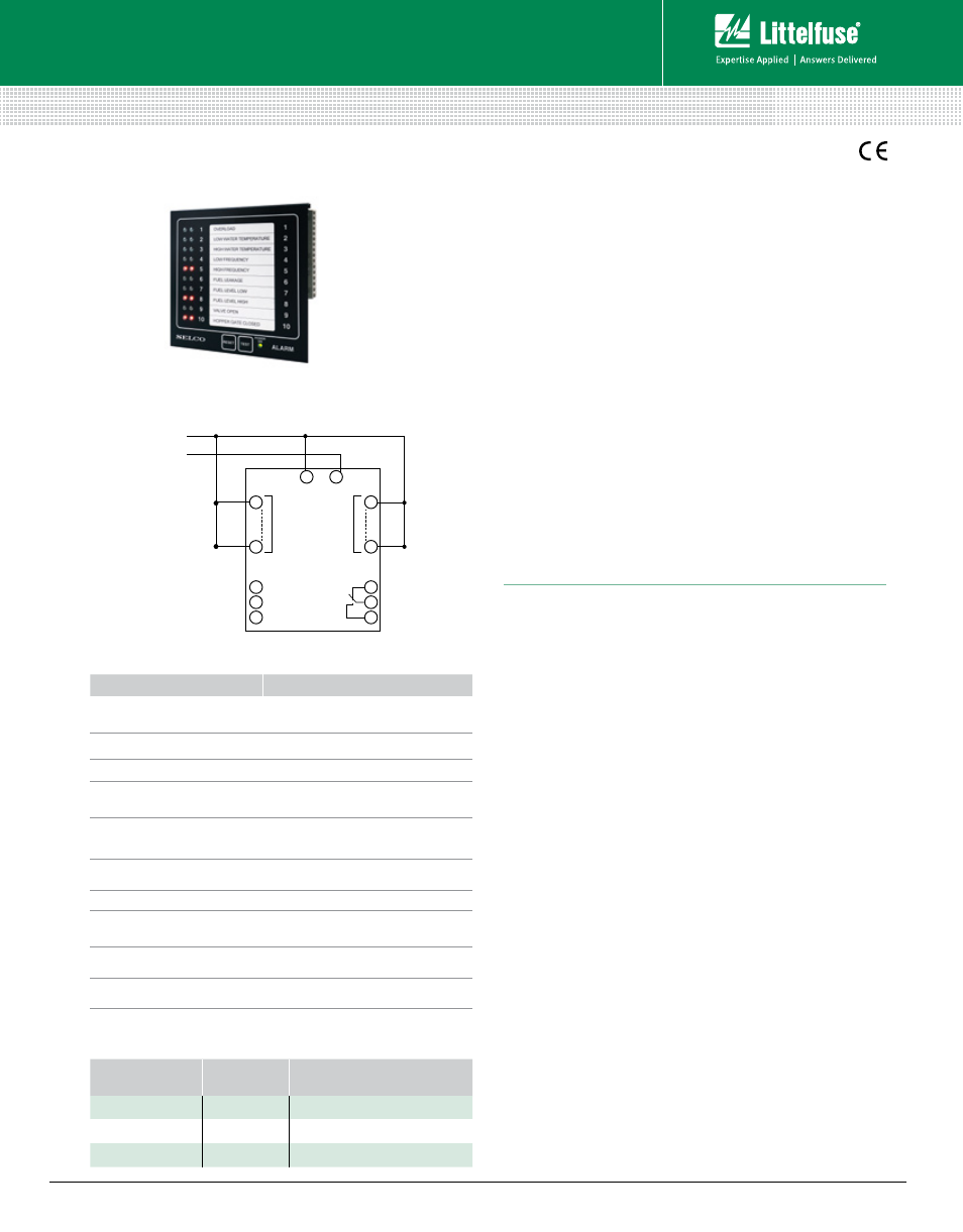
Alarm Monitor
Ordering
nuMber
cOntrOl
pOwer
FunctiOn
M1000.0040
48-110 Vdc
IP54 front
M1000.0080
12-24 Vdc
IP54 front
M1000.0220
12-24 Vdc
Internal siren, IP54 at front
Description
The M1000 is an alarm panel with 10 digital inputs. Inputs from
a dry contact (normally open [NO] or normally closed [NC])
will cause the corresponding LED to flash. Simultaneously a
common alarm output and a siren output will be activated as
well as an individual output. The unit has separate indications
of first alarm, following alarms and acknowledged alarms. It
also has dedicated inputs for remote reset and blocking. The
unit can be configured for cable monitoring and monitoring of
its own supply and insulation level.
Multiple M1000 units can be interconnected to form a large
scale alarm system. In this situation functions are available
for synchronizing the flashing of the LEDs and enabling
global indication of first alarm for all connected units. Alarm
related parameters like time delays, reset functions and other
features can be configured through 18 programming switches.
The M1000 can also be configured via the RS232 interface.
A standard ANSI/VT100 terminal is used as programming
tool. The M1000 is equipped with a 2-wire RS485 interface
supporting MODBUS-RTU communication.
Ordering Information
Simplified Circuit Diagram
FeatureS
beneFitS
10 configurable
digital inputs
Supports both NO and NC input contacts
11 open collector outputs
Allows external control and remote indication
1 siren relay output
Direct connection of alarm siren
Special indication of
first alarm
Provides clear alarm overview in
larger systems
Multiple units can be
connected as one system
Modular and scalable solution
Voltage and insulation
monitoring
Replaces voltage and insulation monitoring
relay on the DC system
Dimming of LEDs
Suitable for bridge consoles
Type-approved by marine
classification societies
Applicable in harsh environments
Configuration by
DIP switches or PC
Easy installation and configuration
RS485 Modbus RTU
Communication with HMI and
SCADA systems
Features & Benefits
Specifications
Voltage Supply
12-24 Vdc-30%/+30% (8-32 Vdc)
48-110 Vdc-30%/+40% (33-155 Vdc)
Max. Power
Consumption
180 mA
Ambient Temp.
–10°C to +70°C (also available for –40°C to +70°C)
Siren Relay Contact 220 Vac/2 A; 30 Vdc/2 A, 30 W
Output
Max. 150 mA per channel
Resistance in
Sensing Cable
Max. 1000 W
Insulation Monitor 25 kW±8 kW (50 kW±10 kW for M1000-11-XXC)
Impulse Test
4.5 kV
1
/
50
μsec.
EMC
CE according to EN50081-1, EN50082-1,
EN50081-2, EN50082-2 and EN61000-2-6
Programming
16 dip-switches or via RS232 interface
Communication
RS485 interface
Weight
0.4 kg
Dimensions
H 144 mm (5.7”); W 144 mm (5.7”);
D 35 mm (1.4”)
Panel Cut-out
H 138 mm (5.4”); W 138 mm (5.4”)
Protection Degree
at Front
IP54 (see Type Description)
www.littelfuse.com/m1000
17
26
10
28
29
30
31
32
11
12
13
1
–
+
TEST
BLOCK
M1000
(Alarm Monitor)
SUPPLY
SIREN
OPEN
COLLECTOR
OUTPUTS
ALARM
INPUT
CONTACTS
RESET
Rev: 4-A-050313