Littelfuse AK3 Series User Manual
Ak3 series, Transient voltage suppression diodes, Axial leaded – 3ka > ak3 series
Transient Voltage Suppression Diodes
© 2014 Littelfuse, Inc.
Specifications are subject to change without notice.
Revised: 03/04/14
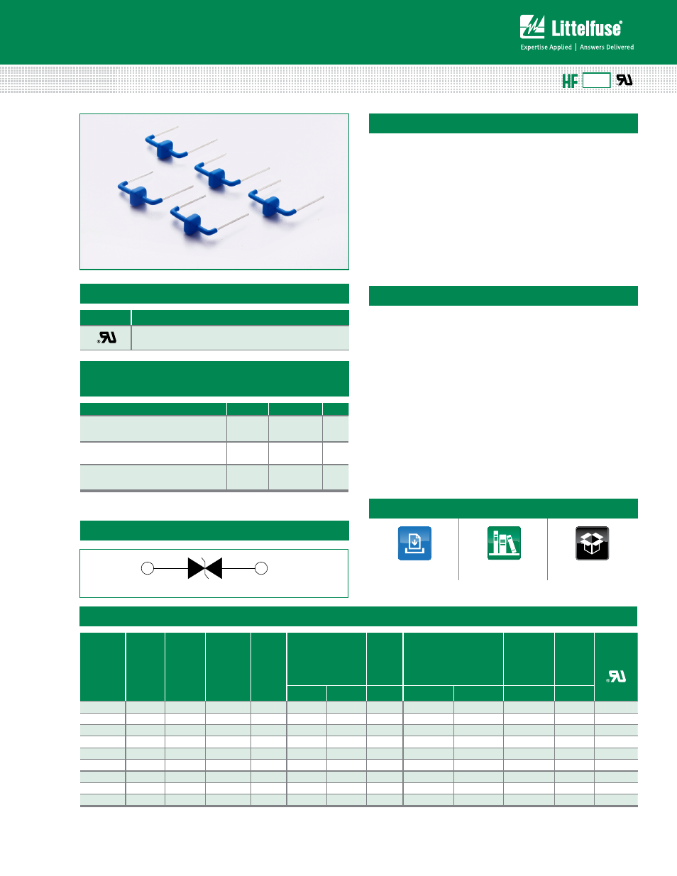
Axial Leaded – 3kA > AK3 series
The AK3 series of high current transient suppressors have
been specially designed for use in A.C. line protection and
any demanding applications (AC or DC). They offer superior
clamping characteristics over standard S.A.D. technologies
by virtue of the Littelfuse Foldbak technology. Therefore,
any voltage rise due to increased current conduction is
contained to a minimum, providing the best possible
protection level. They can also be connected in series and/
or parallel to create very high capacity protection solutions.
Description
Features
Agency Approvals
Electrical Characteristics
.
(T
A
=25°C unless otherwise noted)
Note: Using 8/20µS wave shape as defined in IEC 61000-4-5.
AGENCY
AGENCY FILE NUMBER
E128662
Maximum Ratings and Thermal Characteristics
(T
A
=25°C unless otherwise noted)
Parameter
Symbol
Value
Unit
Operating Storage Temperature
Range
T
STG
(-)55 to 150
°C
Operating Junction Temperature
Range
T
J
(-)55 to 125
ºC
Current Rating
1
I
PP
3
kA
Note:
1. Rated I
PP
measured with 8/20μs pulse.
• Very low clamping voltage
• Ultra compact: less
than one-tenth the size
of traditional discrete
solutions
• Sharp breakdown voltage
• Low slope resistance
• Bi-directional
• Foldbak technology for
superior clamping factor
• Symmetric in leads width
for easier soldering during
assembly
• IEC-61000-4-2 ESD
15kV(Air), 8kV (Contact)
• ESD protection of data
lines in accordance with
IEC 61000-4-2 (IEC801-2)
• EFT protection of data
lines in accordance with
IEC 61000-4-4 (IEC801-4)
• Halogen-free
• RoHS compliant
• Glass passivated junction
RoHS
AK3 Series
Functional Diagram
Part
Numbers
Part
Marking
Standoff
Voltage
(V
SO
)
Volts
Max.
Reverse
Leakage
(I
R
) @V
SO
µA
Typical
I
R
@
85°C
(µA)
Reverse
Breakdown
Voltage (V
BR
) @ I
T
Test
Current
I
T
Max. Clamping Voltage
V
CL
@ I
pp
Peak Pulse
Current (I
PP
) (Note 1)
Max. Temp
Coefficient
OF V
BR
Max.
Capaci-
tance
0 Bias
10kHz
Agency
Approval
Min Volts Max Volts
(mA)
V
CL
Volts
I
PP
Amps
(%/°C)
(nF)
AK3 - 015C 3-015C
15
10
15
16
19
10
28
3,000
0.1
9.0
X
AK3 - 030C 3-030C
30
10
15
32
37
10
90
3,000
0.1
11.0
X
AK3 - 058C 3-058C
58
10
15
64
70
10
110
3,000
0.1
6.0
X
AK3 - 066C 3-066C
66
10
15
72
80
10
120
3,000
0.1
6.0
X
AK3 - 076C 3-076C
76
10
15
85
95
10
140
3,000
0.1
6.0
X
AK3 - 150C 3-150C
150
10
15
158
194
10
230
3,000
0.1
2.6
X
AK3 - 170C 3-170C
170
10
15
179
220
10
260
3,000
0.1
2.4
X
AK3 - 380C 3-380C
380
10
15
401
443
10
520
3,000
0.1
2.0
X
AK3 - 430C 3-430C
430
10
15
440
490
10
625
3,000
0.1
2.0
X
Bi-directional
Uni-directional
Cathode
Anode
Additional Information