Littelfuse T4900 Series User Manual
T4900 series, Generator control, Basic
Generator Control
© 2013 Littelfuse Protection Relays & Controls
Features
BeNeFIts
Adjustable delta voltage,
stability and % VAR load
deviation by front panel
potentiometers
Facilitates adjustment during installation and
commissioning. VAR Load deviation adjustment
enables paralleling of differenst size generators
Inputs for disabling internal
voltage control
Enables operation where system voltage is set
externally such as in grid-parallel operation
Power factor control
function
Enabling alternative use as power factor
controller, thus maintaining fixed power factor
(cos phi) in installations with fluctuating
inductive loads
Visual indication of voltage,
increase/decrease and
unload signals
Provides quick and concise status information
Direct line-line voltage
supply (up to 690 Vac)
Simplifies design and installation. No need for
PTs or separate power supply
Galvanic isolated inputs
Protects the unit against high AC voltage and
currents from the installation including spikes
DIN-rail or screw mount
Easy installation
Basic
t4900 serIes
VAR Load Sharer
Description
The T4900 VAR Load Sharer provides automatic load sharing
of reactive power [kVAR] and voltage control for parallel
running generators. The reactive load on each generator is
compared with the reactive load on the other generators
and corrected on the AVR (Automatic Voltage Regulator)
until balance is obtained. The T4900 can also be used for
power factor (PF) control in applications where one or more
generators are operated in parallel with the grid (utility). The
input to the T4900 are the voltage and the current from which
the reactive power and voltage is determined. The T4900
calculates I x sin φ, representing the reactive load.
Power factor control for parallel operation with the public
grid can be obtained by connecting an external contact
between terminals 12 (COM) and 28 (PF ON). The setting is
determined by an external potentiometer (100 kW) across
terminals 29 and 30 (PF-SET).
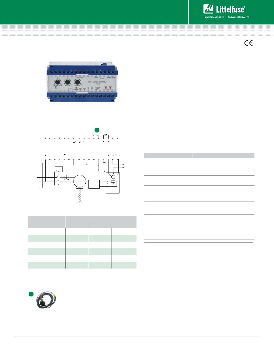
Simplified Circuit Diagram
Features & Benefits
Other supply voltages, nominal currents and combinations are available on request.
Specifications
Max. Voltage
660 V
Voltage Range
110%
Voltage Dev. Adjustment 0- ±12 V
Consumption
Voltage 4 VA at U
N
Current 0.4VA at I
N
Continuous Current
2 x I
N
Frequency Range
35-70 Hz
Proportional Band
±25-125% load
Dead Band Zone
±1-10% load
Contact Rating
AC: 400 V, 2 A, 250 VA; DC: 110 V, 2 A, 100 W
Operating Temperature –20°C to +70°C
EMC
CE according to EN50081-1, EN50082-1,
EN50081-2, EN50082-2
Burn-in
50 hours before final test
Enclosure Material
Polycarbonate, flame retardant
Weight
0.7 kg
Dimensions
H 70 mm (2.7“); W 150 mm (5.9“); D 115 mm (4.5“)
Installation
35 mm DIN rail or 4 mm (
3
/
16
”) screws
www.littelfuse.com/t4900
OrderINg NumBer
termINals
I
N
1-3
2-3
T4900.0010
450 V
400 V
5 A
T4900.0020
230 V
–
5 A
T4900.0030
480 V
415 V
5 A
T4900.0040
110 V
63 V
5 A
T4900.0050
127 V
120 V
1 A
T4900.0060
110 V
100 V
1 A
Ordering Information
BUS
U
N
I
N
GEN
AVR
M
1
2
3
4
5
6
7
8
9
10
11
12
12
12
1
2
3
4
5
6
13
13
14
15
16
17
18
19
20
21
22
23
24
25
26
27
28
29
30 31
32
L
1
L
2
L
3
UNLOAD
UNLOAD or
PF=1.0
PF=1.0 – 0.7 ind.
100 K
NEXT
T4900
E7800
(Motorized
Potentiometer)
COM.
PARALLEL
LINES
INCR. DECR.
POWER FACTOR
VOLT
OUT
VOLT
IN
PF–SET.
PF ON
TRIP ENABLE
WATT
IN
TEST
OUT
–
–
+
T4900
(VAR Load Sharer)
T4910-07 Potentiometer with Cable for
External Power Factor Setting
External contact between terminals
12 (COM) and 28 (PF ON). Included.
Accessories
A
A
Rev: 4-A-050313