Teccor, Brand thyristors, 12 amp alternistor (high communitation) triacs – Littelfuse Qxx12xHx Series User Manual
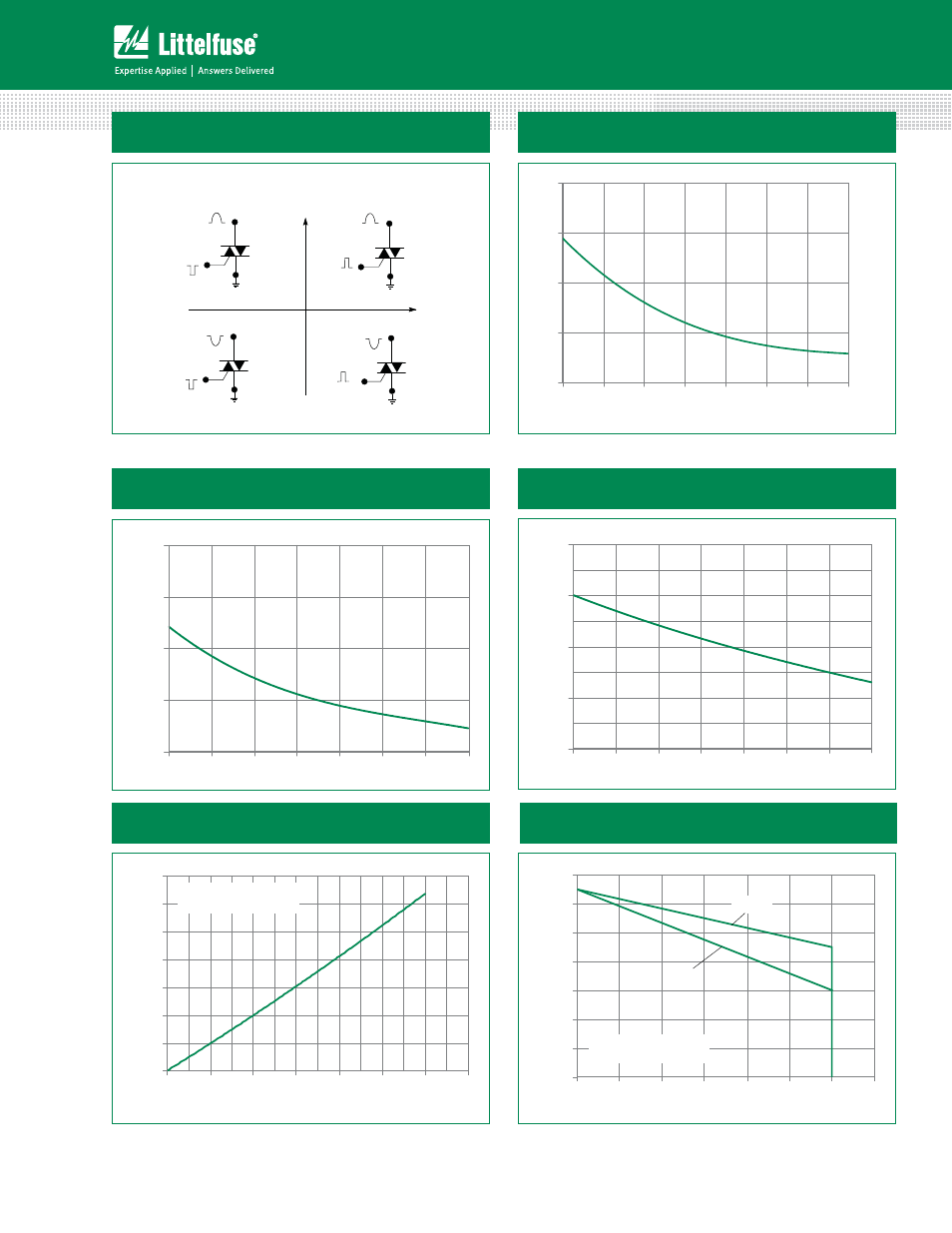
Page 3: Figure 1: definition of quadrants
109
Revised: 09/23/13
©2013 Littelfuse, Inc
Specifications are subject to change without notice.
Teccor
®
brand Thyristors
12 Amp Alternistor (High Communitation) Triacs
Qxx12xHx Series
Figure 2: Normalized DC Gate Trigger Current for
All Quadrants vs. Junction Temperature
0.0
1.0
2.0
3.0
4.0
Junction Temperature (T
J
) - C
Ratio of
I
GT
/ I
GT
(T
J
= 2
5
ºC)
-65 -40 -15 10 35 60 85 110
Figure 1: Definition of Quadrants
Note: Alternistors will not operate in QIV
MT2 POSITIVE
(Positive Half Cycle)
MT2 NEGATIVE
(Negative Half Cycle)
MT1
MT2
+
I
G T
REF
QII
MT1
I
G T
GATE
MT2
REF
MT1
MT2
REF
MT1
MT2
REF
QI
QIV
QIII
ALL POLARITIES ARE REFERENCED TO MT1
(
-
)
I
G T
GATE
(+)
I
G T
-
I
G T
GATE
(
-
)
I
G T
GATE
(+)
+
-
Figure 3: Normalized DC Holding Current
vs. Junction Temperature
0.0
1.0
2.0
3.0
4.0
-65 -40 -15 10 35 60 85 110
Junction Temperature (T
J
) - ºC
Ratio of
I
H
/ I
H
(T
J
= 2
5
ºC)
Figure 4: Normalized DC Gate Trigger Voltage for
All Quadrants vs. Junction Temperature
0.0
0.5
1.0
1.5
2.0
-65 -40 -15 10 35 60 85 110
Junction Temperature (T
J
) - ºC
Ratio of V
GT
/ V
GT
(T
J
= 2
5
ºC)
0
2
4
6
8
10
12
14
0
2
4
6
8
10
12
14
RMS On-State Current [I
T(RMS)
] -- Amps
Av
e
ra
g
e
O
n
-S
tate
P
o
wer D
is
s
ip
a
ti
o
n
[P
D(
AV
)
] --
Watts
CURRENT WAVEFORM: Sinusoidal
LOAD: Resistive or Inductive
CONDUCTION ANGLE: 360°
Figure 5: Power Dissipation (Typical)
vs. RMS On-State Current
Figure 6: Maximum Allowable Case Temperature
vs. On-State Current
60
70
80
90
100
110
120
130
0
2
4
6
8
10
12
14
RMS On-State Current [I
T(RMS)
] - Amps
Maximum Allowable Case Temperature
(T
C
) - °C
CURRENT WAVEFORM: Sinusoidal
LOAD: Resistive or Inductive
CONDUCTION ANGLE: 360°
Qxx12RH5
Qxx12NH5
Qxx12LH5