Varistor products – Littelfuse DHB34 Varistor Series User Manual
Page 4
© 2013 Littelfuse, Inc.
178
Revised: May 8, 2013
Varistor Products
DHB34 Varistor Series
Industrial High Energy Terminal Varistors > DHB34 Series
Specifications are subject to change without notice.
Please refer to www.littelfuse.com/series/dhb34.html for current information.
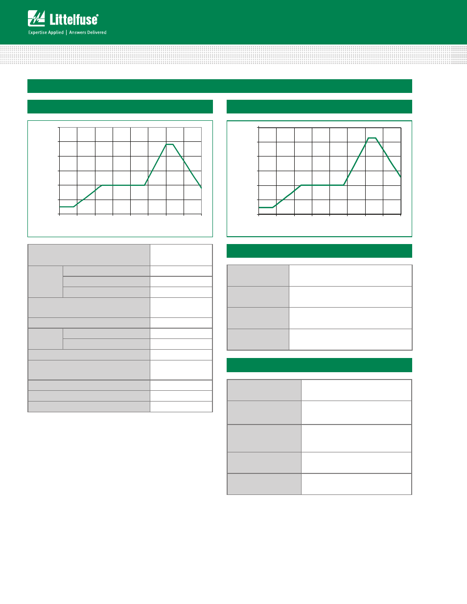
Reflow Condition
Pb – Free assembly
Pre Heat
- Temperature Min (Ts(min))
150°C
- Temperature Max (Ts(max))
200°C
- Time (min to max) (ts)
60 – 180 secs
Average ramp up–rate (Liquidus Temp (TL)
to peak
5°C/second max
TS(max) to TL - Ramp-up Rate
5°C/second max
Reflow
- Temperature (TL) (Liquidus)
217°C
- Temperature (tL)
60 – 150 seconds
Peak Temperature (TP)
250
+0/-5
°C
Time within 5°C of actual peak
Temperature (tp)
20 – 40 seconds
Ramp-down Rate
5°C/second max
Time 25°C to peak Temperature (TP)
8 minutes Max.
Do not exceed
260°C
Soldering Parameters
Operating/Storage
Temperature
-55°C to +85°C/-55°C to +125°C
Humidity Aging
+85°C, 85% RH, 1000 hours
+/-10% Voltage change
Thermal Shock
+85°C to -40°C 5 times
+/-10% Voltage change
Solvent Resistance
MIL–STD–202, Method 215F
Moisture Sensitivity
Level 1, J–STD–020C
Lead Material
Tin–coated Copper
Soldering
Characteristics
Solderability per MIL–STD–202,
Method 208E
Insulating Material
Cured, flame retardant epoxy polymer
meets UL94V–0 requirements.
Device Labeling
Marked with LF, voltage, amperage rating,
and date code.
Physical Specifications
Environmental Specifications
Lead–free Profile
Non Lead–free Profile
0
50
100
150
200
250
300
0
0.5
1
1.5
2
2.5
3
3.5
4
TIME(MINUTES)
T
E
M
P
E
RAT
URE
(
ºC)
Maximum Wave 240C
0
50
100
150
200
250
300
0
0.5
1
1.5
2
2.5
3
3.5
4
TIME(MINUTES)
T
EMPER
A
T
U
R
E
(º
C
)
Maximum Wave 260C
Figure 5
Figure 6