Teccor, Brand thyristors, Multipulse™ sidacs – Littelfuse Kxxx1G Series User Manual
Page 2: Figure 1: characteristics, Figure 4: v, Change vs. junction temperature
2
Revised: 12/26/13
©2013 Littelfuse, Inc
Specifications are subject to change without notice.
Teccor
®
brand Thyristors
Multipulse™ SIDACs
Kxxx1G Series
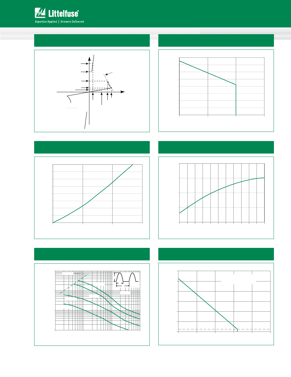
Figure 1: Characteristics
-V
+I
V
DRM
+V
V
S
I
S
I
H
R
S
I
DRM
I
BO
V
BO
V
T
I
T
(V
BO
- V
S
)
(I
S
- I
BO
)
R
S
=
-I
RMS On-State Current (Amps)
2.0
1.5
1.0
0
50
Maximum
All
ow
able Lead
Te
mper
at
ur
e (°C)
60
70
80
90
100
110
120
130
RMS On-State Current (Amps)
Av
er
ag
e P
D
(W
at
ts)
1.5
1.0
0.5
0.0
0.0
0.5
1.0
1.5
2.0
2.5
3.0
3.5
4.0
Figure 3: Power Dissipation (Typical)
vs. On-State Current
Figure 2: Maximum Allowable Lead/Tab Temperature
vs. On-State Current
Junction Temperature (°C)
Nor
maliz
ed
Pe
rcentag
e of
V
BO
Chang
e (%)
-40
-25
-10
5
20
35
50
65
80
95
110
125
-10.0
-5.0
0.0
5.0
10.0
Figure 4: V
BO
Change
vs. Junction Temperature
1
10
100
1000
1
10
100
1000
5KHz
1KHz
60 Hz
f = 5Hz
Pulse Base Width (t
O
)-µs
T
J
=125˚C
Repetitive Peak On-State
Current (I
TRM
)-Amps
I
TM
t
O
1/f
di/dt limit
Figure 5: Pulse On-State
Current Rating
Figure 6: Maximum Allowable Ambient Temperature
vs. On-State Current
25
20
40
60
80
100
120
140
0.0
0.2
0.4
0.6
0.8
1.0
RMS On-State Current [I
T(RMS)
] - Amps
M
axi
mu
m
Al
lowa
bl
e
Am
bie
nt
Te
mp
erat
ur
e
(T
A
) -
°C
CURRENT WAVEFORM: Sinusoidal - 60Hz
LOAD: Resistive or Inductive
FREE AIR RATING