Varistor products, Radial lead varistors > ultramov, 25s series – Littelfuse UltraMOV 25S Varistor Series User Manual
Page 2
© 2013 Littelfuse, Inc.
108
Revised: May 8, 2013
Varistor Products
Specifications are subject to change without notice.
Please refer to www.littelfuse.com/series/ultramov25s.html for current information.
UltraMOV™ 25S Varistor Series
Radial Lead Varistors > UltraMOV
TM
25S Series
UltraMOV™ 25S Series Ratings & Specifications
Part
Number
Branding
Maximum Rating (85°C)
Specifications (25°C)
Continuous
Transient
Varistor Voltage
at 1mA DC
Test Current
Maximum
Clamping
Voltage at 100A,
8 x 20μs
UL 1449 ed.3
Voltage
Protection
Rating
Typical
Capaci-
tance
f = 1MHz
AC Volts DC Volts
Energy
2ms
Peak Surge
Current
8 x 20μs
V
M(AC)RMS
V
M(DC)
W
TM
1 x
Pulse
I
TM
1 x Pulse
V
NOM
Min
V
NOM
Max
V
C
VPR
C
(V)
(V)
(J)
(A)
(V)
(V)
(pF)
V25S115P
P25S115
115
150
230
22000
162
198
295
400
4500
V25S130P
P25S130
130
170
255
22000
184
226
335
500
3900
V25S140P
P25S140
140
180
285
22000
200
240
355
500
3500
V25S150P
P25S150
150
200
300
22000
216
264
390
500
3200
V25S175P
P25S175
175
225
315
22000
243
297
450
600
2550
V25S230P
P25S230
230
300
400
22000
324
396
585
700
1900
V25S250P
P25S250
250
320
435
22000
351
429
640
800
1750
V25S275P
P25S275
275
350
470
22000
387
473
700
900
1610
V25S300P
P25S300
300
385
500
22000
423
517
765
1000
1450
V25S320P
P25S320
320
420
540
22000
459
561
825
1000
1350
V25S385P
P25S385
385
505
630
22000
558
682
1010
1200
1080
V25S420P
P25S420
420
560
655
22000
612
748
1100
1500
1000
V25S440P
P25S440
440
585
675
22000
643
787
1160
n/a
900
V25S460P
P25S460
460
615
690
22000
675
825
1220
n/a
870
V25S510P
P25S510
510
670
700
22000
738
902
1335
n/a
820
V25S550P
P25S550
550
745
765
22000
819
1001
1475
n/a
750
V25S625P
P25S625
625
825
800
22000
900
1100
1625
n/a
660
V25S750P
P25S750
750
970
890
22000
1080
1320
1950
n/a
550
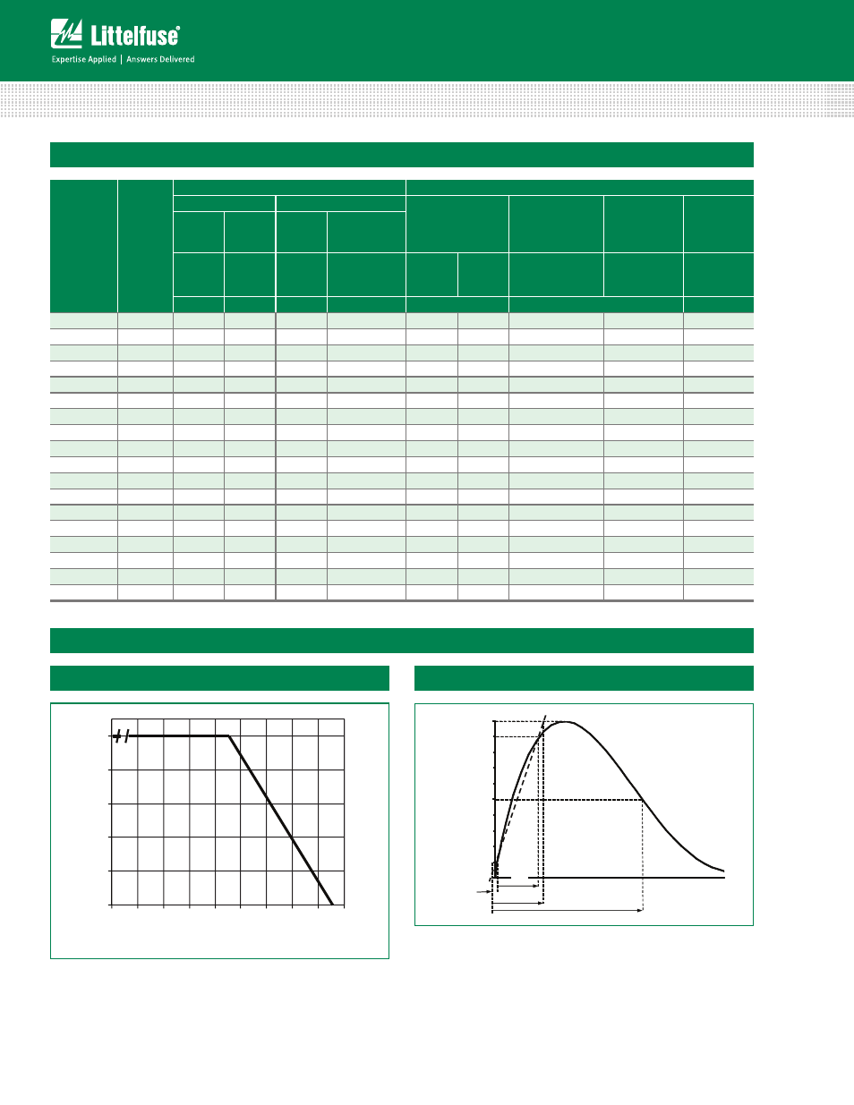
Note: Average powder dissipation of transients should not exceed 1.5 watts.
For applications exceeding 85ºC ambient temperature, the
peak surge current and energy ratings must be reduced as
shown above.
Peak Current, Energy and Power Derating Curve
0
20
40
60
80
100
55
50
60
70
80
90
100 110 120 130
P
E
RCE
NT
O
F
RA
T
E
D
V
A
L
UE
AM BIEN T T EM PER AT U R E (ºC )
0
50
100
PER
C
EN
T O
F
PEAK VAL
U
E
T IM E
t
1
t
2
t
O
1
Peak Pulse Current Test Waveform for Clamping Voltage
Transient V-I Characteristics Curves
0
1
= Virtual Origin of Wave
T = Time from 10% to 90% of Peak
T
1
= Rise Time = 1.25 x T
T
2
= Decay Time
Example - For an 8/20 μs Current Waveform:
8μs = T
1
= Rise Time
20μs = T
2
= Decay Time
Figure 1
Figure 2