Teccor, Brand thyristors, Ev series 0.8 amp sensitive triacs – Littelfuse LX8 Series User Manual
Page 3: Figure 1: definition of quadrants
29
Revised: 09/23/13
©2013 Littelfuse, Inc
Specifications are subject to change without notice.
Teccor
®
brand Thyristors
EV Series 0.8 Amp Sensitive Triacs
LX8 Series
Figure 1: Definition of Quadrants
MT2 POSITIVE
(Positive Half Cycle)
MT2 NEGATIVE
(Negative Half Cycle)
MT1
MT2
+
I
G T
REF
QII
MT1
I
G T
GATE
MT2
REF
MT1
MT2
REF
MT1
MT2
REF
QI
QIV
QIII
ALL POLARITIES ARE REFERENCED TO MT1
(
-
)
I
G T
GATE
(+)
I
G T
-
I
G T
GATE
(
-
)
I
G T
GATE
(+)
+
-
Junction Temperature (T
J
) °C
Ratio of
I
GT
(T
J
= 2
5
ºC)
I
GT
I
H
(T
J
= 2
5
ºC)
-55
-40
-15
+5
+25
+45
+65
+85
+110
0.0
1.0
2.0
3.0
INITIAL ON-STATE CURRENT = 100mA (DC)
+125
I
H
Ratio of
0.5
1.5
2.5
Junction Temperature (T
J
) °C
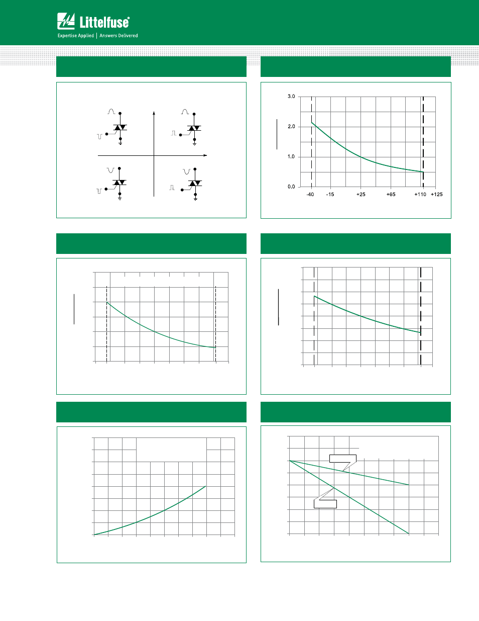
Figure 3: Normalized DC Holding Current
vs. Junction Temperature
Figure 2: Normalized DC Gate Trigger Current for
All Quadrants vs. Junction Temperature
Figure 4: Normalized DC Gate Trigger Voltage for
All Quadrants vs. Junction Temperature
-55
-40
-15
+5
+25
+45
+65
+85
0.0
0.50
1.00
1.50
2.00
+125
V
GT
Ratio of
+110
0.25
0.75
1.25
1.75
Junction Temperature (T
J
) °C
V
GT
(T
J
= 2
5
ºC)
A
v
er
ag
e On-stat
e P
o
w
er Dissipation
[P
D(A
V)
] -
W
a
tt
s
0.0
0.1
0.2
0.3
0.4
0.5
0.6
0.0
0.25
0.50
0.75
1.00
1.25
1.50
1.75
2.00
RMS On-state Current [I
T(RMS)
] - Amps
CURRENT WAVEFORM: Sinusoidal
LOAD: Resistive or Inductive
CONDUCTION ANGLE: 360˚
0.7
0.8
0.9
1.0
Figure 5: Power Dissipation (Typical)
vs. RMS On-State Current
Figure 6: Maximum Allowable Case Temperature
vs. On-State Current
0.0
0.1
0.2
0.3
0.4
0.5
0.6
0.7
0.8
50
60
70
80
90
100
110
130
RMS On-state Current [ I
T(RMS)
] - Amps
Maximum Allo
w
able
Case
Temper
at
ur
e
(T
C
) - ˚C
1.0
0.9
120
TO-92
SOT-223
CURRENT WAVEFORM: Sinusoidal
LOAD: Resistive or Inductive
CONDUCTION ANGLE: 360
o
CASE TEMPERATURE: Measured as
shown on dimensional drawings