Transient voltage suppression diodes, Tvs diode arrays, Surface mount – 1500w > smcj-hr series – Littelfuse SMCJ-HR Series User Manual
Page 3: Family of products), I-v curve characteristics, Figure 2 - peak pulse power rating, Group b test requirement
Transient Voltage Suppression Diodes
43
TVS Diode Arrays
(SPA
™
Family of Products)
©2013 Littelfuse, Inc.
Specifications are subject to change without notice.
Revised: 10/22/13
Surface Mount – 1500W > SMCJ-HR series
SMCJ-HR Series
43
TVS Diode Arrays
(SPA
™
Family of Products)
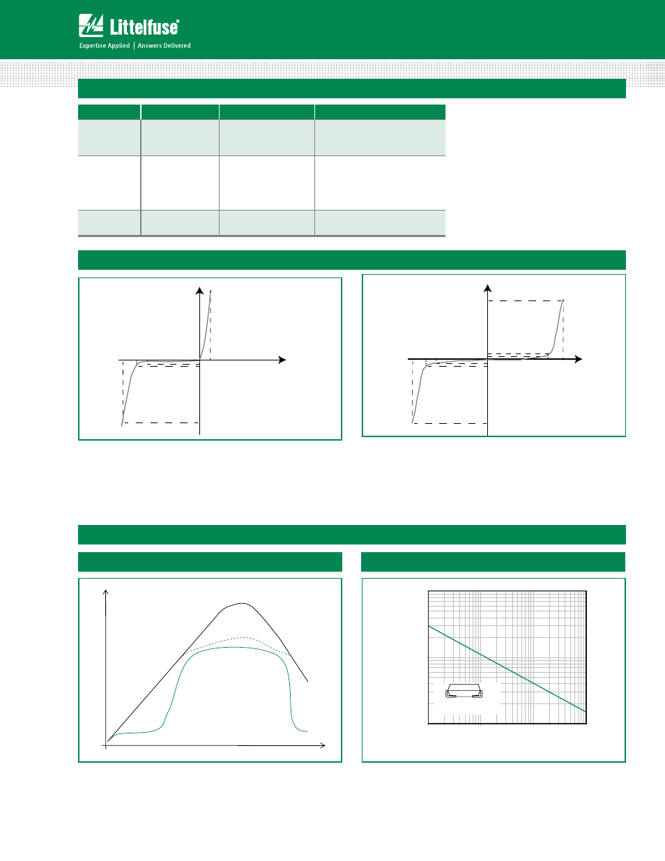
I-V Curve Characteristics
Voltage Transients
Time
Voltage Across TVS
Current Through TVS
Voltage or Current
Figure 1 - TVS Transients Clamping Waveform
Ratings and Characteristic Curves
(T
A
=25°C unless otherwise noted)
1
10
100
0.000001
0.00001
0.0001
0.001
t
d
-Pulse Width (sec.)
P
PPM
-Peak Pulse Power (kW)
0.31x0.31" (8.0x8.0mm)
Copper Pad Area
Figure 2 - Peak Pulse Power Rating
Vc V
BR
V
R
I
R
I
T
I
pp
V
Uni-directional
V
F
Vc V
BR
V
R
I
R
I
T
I
pp
V
Vc
V
BR
V
R
I
pp
I
R
I
T
Bi-directional
P
PPM
Peak Pulse Power Dissipation -- Max power dissipation
V
R
Stand-off Voltage -- Maximum voltage that can be applied to the TVS without operation
V
BR
Breakdown Voltage -- Maximum current that flows though the TVS at a specified test current (I
T
)
V
C
Clamping Voltage -- Peak voltage measured across the suppressor at a specified Ippm (peak impulse current)
I
R
Reverse Leakage Current -- Current measured at V
R
V
F
Forward Voltage Drop for Uni-directional
continues on next page.
3
Group B Test Requirement
Screen
Method
Condition
Requirement
Surge test
10/1000
µ
s Peak
Pluse Waveform
Maximum Clamping
Voltage (V
C
) @ Peak
Plus Current (I
PP
)
Sample size 45 perform 10x
Accept 0 failures
Burn - In
(HTRB)
MIL
-STD-750,
Method 1038.5
Applied Voltage
100% V
R
@150°C
Sample size 45
340 hours (680 hours for
bi-direction products, each
direction 340 hours)
Accept 0 failures
Electrical test
--
I
R
@V
R
, V(
BR
)@I
T
Sample size 45
Accept 0 failures