Littelfuse MPS-469X (PGR-6310) Series User Manual
Protection relays & controls, Motor protection relay retrofits, Motor protection retrofit kits description
Protection Relays & Controls
© 2013 Littelfuse Protection Relays & Controls
Littelfuse.com/relayscontrols
Motor Protection Relay Retrofits
MPu-32-X69X (PGR-6210) SERIES and MPS-469X (PGR-6310) SERIES
Motor Protection Retrofit Kits
Description
Littelfuse Startco retrofit kits are an excellent choice
for upgrading motor protection, providing current- and
temperature-based protection, metering, and data logging.
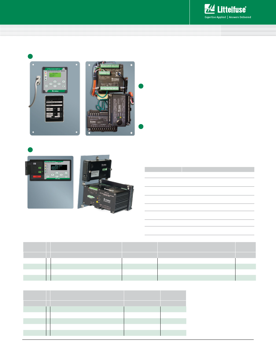
MPU-32-X69X
The MPU-32-X69X Motor Protection Retrofit Kit is designed
to replace GE Multilin 169, 269, and 369 relays. It includes
the MPU-32 Motor Protection Relay, MPU-CIM Current Input
Module, and optional MPS-RTD Temperature Input Modules,
which are pre-wired on a panel. The kit fits in the existing
space and typically can utilize existing current transformers
and wiring to simplify the upgrade procedure.
MPS-469X
The MPS-469X Motor Protection Retrofit Kit replaces the
GE Multilin 469 relay. It includes the MPS Motor Protection
System and optional RTD and differential modules mounted
on a panel that can be installed in the existing 469 cutout.
Existing current transformer and wiring can be utilized,
simplifying the upgrade procedure.
Front
Front
MPU-32-X69X
MPS-469X
Back
Back
MPU-32-X69X Ordering Information
MPS-469X Ordering Information
RTd InPuTS
MPu-32
CoMMunICaTIonS
GRound-FaulT CT
FuTuRE
oPTIonS
MPu-32-X69X –
X
X
X
00
0 = One Platinum 100 Ω
0 = TIA232
0 = Wired for Sensitive Ground-Fault CT (50 mA Secondary)
1 = One Platinum 100 Ω and 8-input MPS-RTD Module 1 = TIA232 & TIA485
1 = Wired for 1- or 5-A Secondary Ground-Fault CT
2 = TIA232 & DeviceNet
4 = TIA232 & Ethernet
ModulE ConFIGuRaTIon
MPS
CoMMunICaTIonS
FuTuRE
oPTIonS
MPS-469X
–
X
X
000
0 = None
1 = RS485
1 = One MPS-RTD Module
2 = RS485 & DeviceNet
2 = Two MPS-RTD Modules
3 = RS485 & Profibus
3 = One MPS-DIF Module
4 = RS485 & Ethernet
4 = One MPS-RTD Module and One MPS-DIF Module
1
2
1
2
FEaTuRES
BEnEFITS
Mounting
Fits in existing mounting holes and panel openings
Quick installation
Existing CTs and RTDs can be used to reduce
installation time
Factory tested
100% factory-tested, pre-assembled components
ensure reliability
Communications
Add communications capability to older switchgear and
improve system performance
Microprocessor based No calibration required saves on maintenance cost
Reduced overcurrent
mode
Maintenance mode setting to reduce the risk of
Arc-Flash Hazards
Conformal coating
Protects circuit boards against corrosion and moisture
Additional protection Additional protective functions, including dynamic thermal
model and ability to match existing overcurrent curves
Features & Benefits
Rev: 4-A-050213