Littelfuse PGR-7200 Series User Manual
Protection relays & controls, Feeder protection unit description, Ordering information simplified circuit diagram
Protection Relays & Controls
© 2013 Littelfuse Protection Relays & Controls
FPU-32 SerieS (PGr-7200)
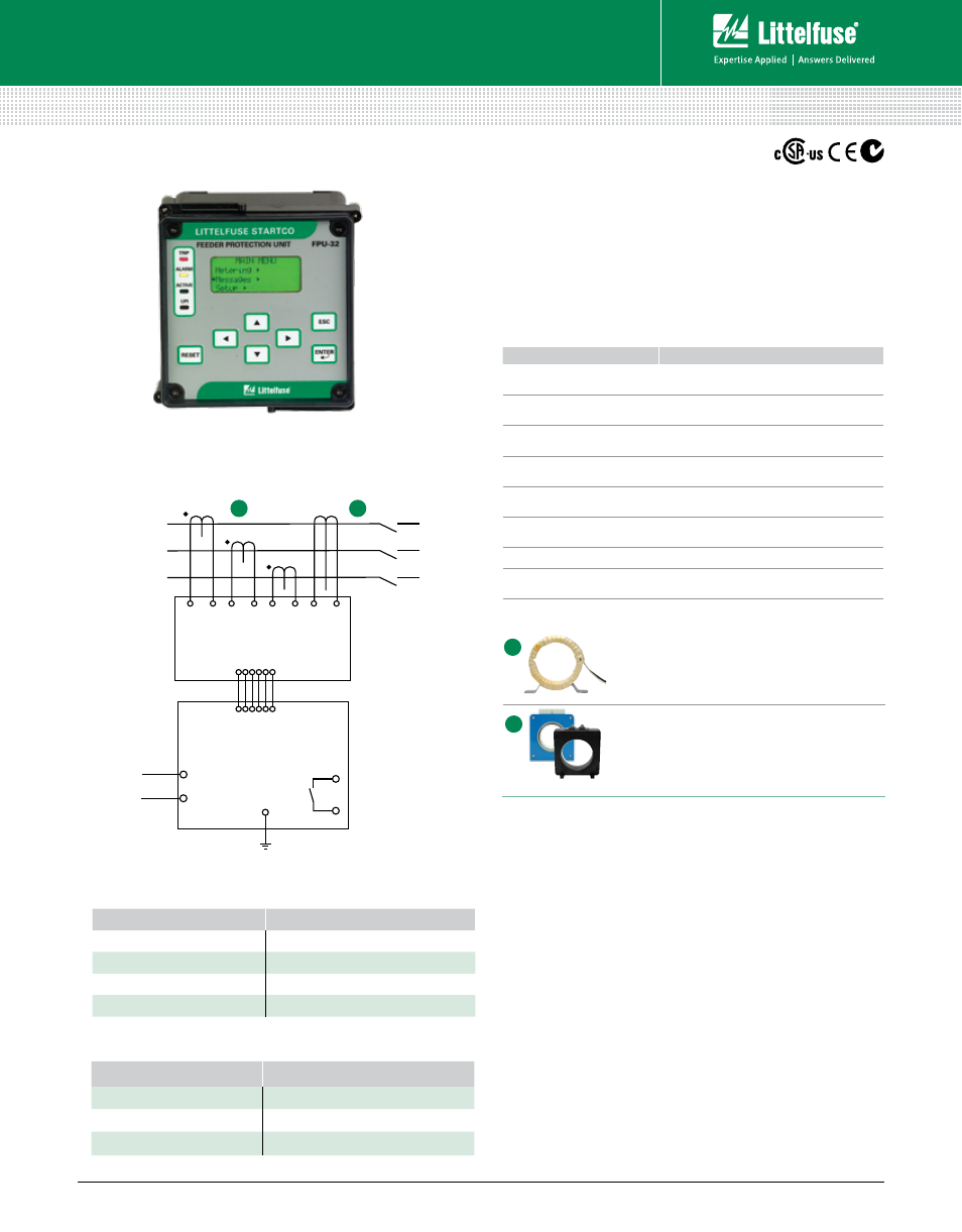
Feeder Protection Unit
Description
The FPU-32 Feeder Protection Unit provides integrated
protection, metering, and data-logging functions. It is an excellent
choice for retrofitting and upgrading older relays because of its
compact size and ability to use existing CTs. The FPU-32 is
used to protect distribution feeders in processing, manufacturing,
petroleum, chemical, and wastewater treatment facilities.
MPU-CIM
(Current Input Module)
(Feeder Protection Unit)
(Feeder Protection Unit)
GF CT
L2
FPU-32
FPU-32
L1
PHASE CT
PHASE CT
CT
PHASE CT
1-A-SECONDARY PHASE CT’s
GF
L2
L1
NOTE: The FPU-32 consists of the Feeder Protection Unit (pictured above) and
the MPU-CIM Current Input Module (not pictured).
OrderinG nUmber
COmmUniCatiOnS
FPU-32-00-00
TIA-232
FPU-32-01-00
TIA-232 & RS-485
FPU-32-02-00
TIA-232 & DeviceNet™
FPU-32-04-00
TIA-232 & Ethernet
NOTE: One of the following is required: MPU-CIM-00-00 Current Input Module, or
MPU-CTI-RT-00 Current Input Module with ring-tonque terminals.
Ordering Information
Simplified Circuit Diagram
FeatUreS
beneFitS
IEC & IEEE overcurrent
protection curves
Definite and inverse time settings for system
coordination; prevents catastrophic failures
Two setpoint groups
Create distinctive settings for maintenance or for
two different loads
Reduced overcurrent
mode
Maintenance mode setting to reduce the risk of
arc-flash hazards
Data logging
On-board 100-event recorder and remote data
logging helps with system diagnostics
Overload
Thermal protection for connected load
Phase loss/Phase reverse
(current)
Detects unhealthy supply conditions
Unbalance (current)
Prevents overheating due to unbalanced phases
Communications
Remotely view measured values, event records
& reset trips
Features & Benefits
A
B
aCCeSSOrieS
reqUirement
Phase CTs
Recommended
Ground-Fault CT
Optional
MPU-16A-Y92A-96N
Optional
Specifications
Protective Functions
(IEEE Device Numbers)
Input Voltage
65-265 Vac, 30 VA; 80-275 Vdc, 25 W
Power-Up Time
800 ms at 120 vac
Ride-Through Time
100 ms minimum
24-Vdc Source
400 mA maximum
AC Measurements
True RMS and DFT, Peak 32 samples/cycle and
positive and negative sequence of fundamental
Frequency
50, 60 Hz
Output Contacts
Three Form C
Approvals
CSA certified, CE, C-Tick (
Australian
)
Communications
TIA-232 (standard); TIA-485, DeviceNet™, Ethernet (optional)
Analog Output
4-20 mA, programmable
Conformally Coated
Standard feature
Warranty
10 years
Mounting
(Control Unit)
Panel (standard)
Surface (with MPU-32-SMK converter kit)
(Current Input Module) DIN, Surface
Overload (49, 51)
Phase sequence (46)
Unbalance (46)
Phase loss (46)
Phase Current Transformers
Phase CTs are required to detect phase
currents.
Ground-Fault Transformer
Zero-sequence current transformer detects
ground-fault current. Available with 5-A and 30-A
primary ratings for low-level pickup.
B
Accessories
A
Definite-time overcurrent (50, 51)
Inverse-time overcurrent (50, 51)
Ground fault (50G/N, 51G/N)
RTD/PTC temperature (49)
Feeder Protection–Standard
Littelfuse.com/fpu-32
Rev: 4-A-050213
Based on Manual Rev 1