Teccor, Brand thyristors, 15 and 16 amp standard scrs – Littelfuse Sxx16x Series User Manual
Page 3
289
Revised: 09/23/13
©2013 Littelfuse, Inc
Specifications are subject to change without notice.
Teccor
®
brand Thyristors
15 and 16 Amp Standard SCRs
Sxx15x & Sxx16x Series
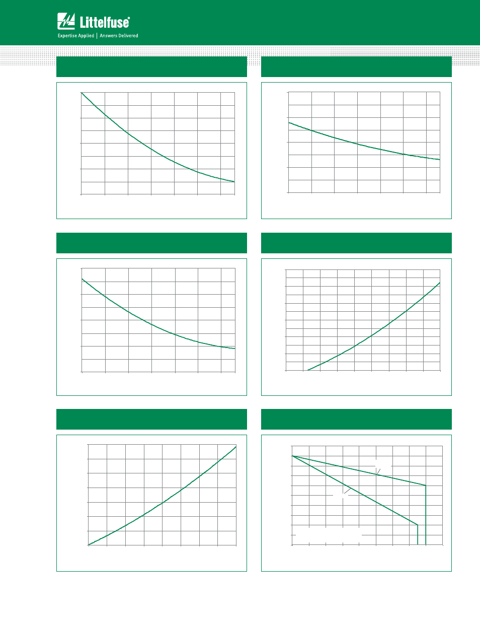
Figure 1: Normalized DC Gate Trigger Current
vs. Junction Temperature
Figure 2: Normalized DC Gate Trigger Voltage
vs. Junction Temperature
125
0.0
0.5
1.0
1.5
2.0
-40
-15
10
35
60
85
110
Junction Temperature (T
J
) -- (ºC)
Ratio of I
GT
/ I
GT
(T
J
= 2
5
°C)
Figure 5: Power Dissipation (Typical)
vs. RMS On-State Current
Figure 6: Maximum Allowable Case Temperature
vs. RMS On-State Current
Figure 3: Normalized DC Holding Current
vs. Junction Temperature
Figure 4: On-State Current vs. On-State
Voltage (Typical)
0.0
0.5
1.0
1.5
2.0
-40
-15
10
35
60
85
110
Junction Temperature (T
J
) -- (°C)
Ratio of
V
GT
/
V
GT
(T
J
= 2
5
ºC)
125
125
0.0
0.5
1.0
1.5
2.0
-40
-15
10
35
60
85
110
Junction Temperature (T
J
) -- (°C)
Ratio of I
H
/ I
H
(T
J
= 2
5
°C)
0
10
20
30
40
50
60
0.7
0.8
0.9
1.0
1.1
1.2
1.3
1.4
1.5
1.6
Instantaneous On-state Voltage (v
T
) – Volts
In
stan
tan
e
o
u
s O
n
-state C
u
rr
en
t
(i
T
) –
Am
p
s
0
2
4
6
8
10
12
14
0
2
4
6
8
10
12
14
16
RMS On-State Current [I
T(RMS)
] - (Amps)
A
v
er
ag
e On-Stat
e P
o
w
er Dissipation
[P
D(A
V)
] - (W
at
ts)
80
85
90
95
100
105
110
115
120
125
130
0
2
4
6
8
10
12
14
16
18
Sxx16R
Sxx16N
Sxx15L
RMS On-State Current [I
T(RMS)
] - Amps
Maximum Allo
w
able
Case
Temper
at
ur
e (T
C
) - °C
CURRENT WAVEFORM: Sinusoidal
LOAD: Resistive or Inductive
CONDUCTION ANGLE: 180°