Sidactor, Protection thyristors, Baseband protection (voice-ds1) – Littelfuse SIDACtor Multiport Series MS-013 User Manual
Page 3: 25°c
SIDACtor
®
Protection Thyristors
145
Revised: February 22, 2011
© 2011 Littelfuse, Inc.
Specifications are subject to change without notice.
Please refer to www.littelfuse.com for current information.
Baseband Protection (Voice-DS1)
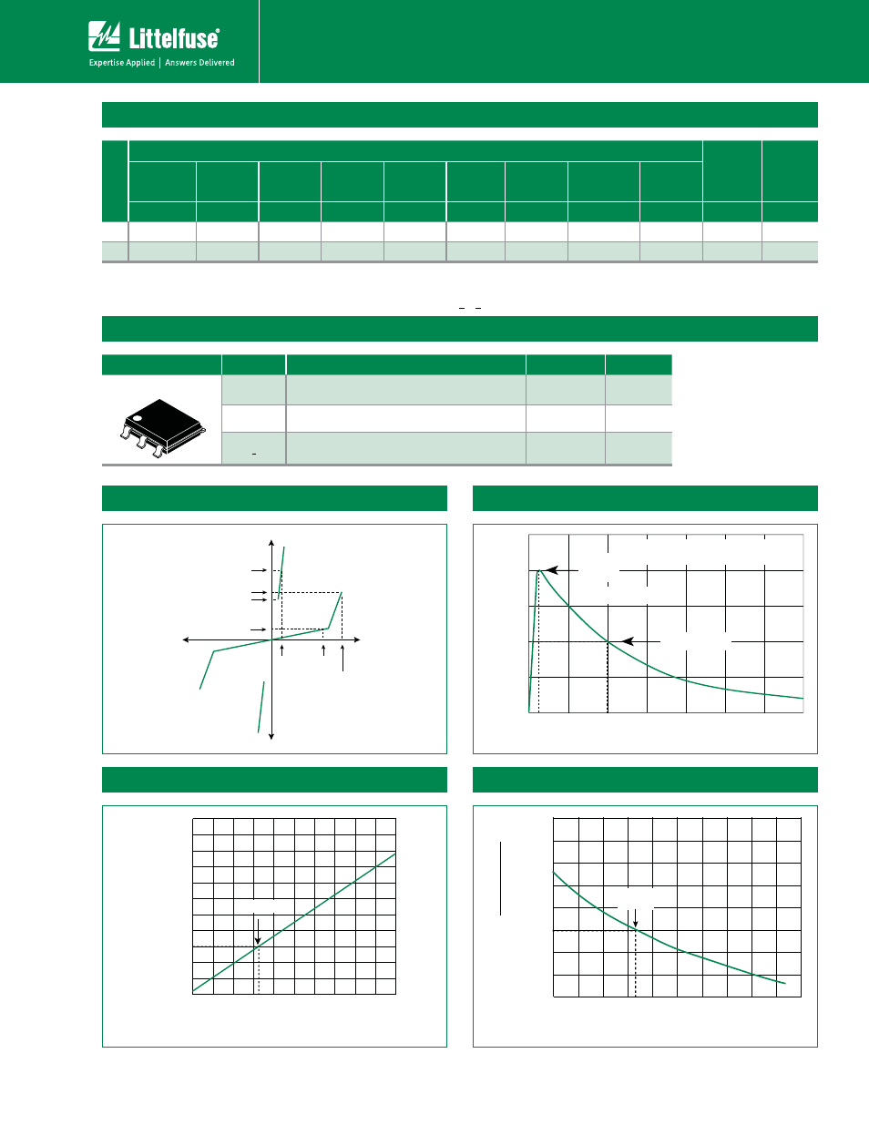
I
H
I
T
I
S
I
DRM
V
DRM
V
T
+V
-V
+I
-I
V
S
50
100
0
t
r
t
d
0
Peak
Value
Half Value
t – Time (μs)
I
PP
– P
eak Pulse Current – %I
PP
t
r
= rise time to peak value
t
d
= decay time to half value
Waveform = t
r
x t
d
V-I Characteristics
t
r
x t
d
Pulse Waveform
25°C
Case Temperature (T
C
) - ºC
2.0
1.8
1.6
1.4
1.2
1.0
0.8
0.6
0.4
-40
-20
0
20
40
60
80
100 120 140 160
R
atio of
I
H
I
H
(T
C
= 25ºC)
Normalized V
S
Change vs. Junction Temperature
Normalized DC Holding Current vs. Case Temperature
Surge Ratings
S
eries
I
PP
I
TSM
di/dt
0.2x310
1
0.5x700
2
2x10
1
2x10
2
8x20
1
1.2x50
2
10x160
1
10x160
2
10x560
1
10x560
2
5x320
1
9x720
2
10x360
1
10x360
2
10x1000
1
10x1000
2
5x310
1
10x700
2
50/60 Hz
A min
A min
A min
A min
A min
A min
A min
A min
A min
A min
A/μs max
A
20
150
150
90
50
75
75
45
75
20
500
C
50
500
400
200
150
200
175
100
200
30
500
Package
Symbol
Parameter
Value
Unit
Modified MS-013
1
2
3
6
5
4
T
J
Operating Junction Temperature Range
UP
°C
T
S
Storage Temperature Range
UP
°C
R
0JA
Thermal Resistance: Junction to Ambient
60
°C/W
Thermal Considerations
-8
-40 -20
0
20 40 60 80 100 120 140 160
-6
-4
0
2
4
6
8
10
12
14
Junction Temperature (T
J
) – °C
P
ercent of
V
S
Change – %
25 °C
Notes:
1 Current waveform in μs
2 Voltage waveform in μs
- Peak pulse current rating (I
PP
) is repetitive and guaranteed for the life of the product.
- I
PP
SBUJOHTBQQMJDBCMFPWFSUFNQFSBUVSFSBOHFPG$UP$
- The device must initially be in thermal equilibrium with -40°C < T
J
<¡$