Littelfuse Fixed Voltage Multiport Series MS-013 User Manual
Sidactor, Protection thyristors, Fixed voltage multiport series - ms-013
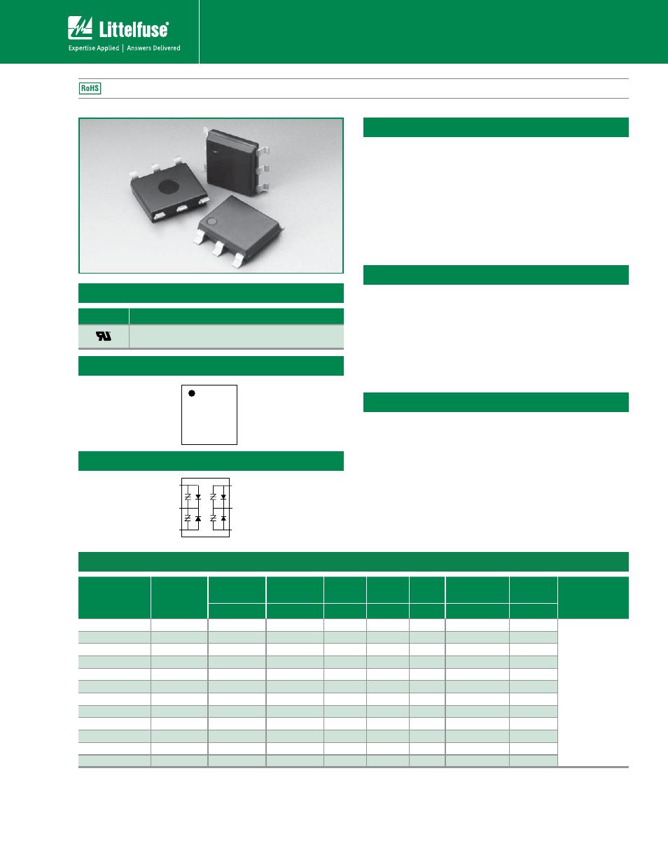
SIDACtor
®
Protection Thyristors
109
Revised: February 22, 2011
© 2011 Littelfuse, Inc.
Specifications are subject to change without notice.
Please refer to www.littelfuse.com for current information.
SLIC Protection
1
4
6
3
2
5
(T
1
)
(R
1
)
(G
1
)
(T
2
)
(R
2
)
(G
2
)
Fixed Voltage Multiport Series - MS-013
Electrical Characteristics
Fixed Voltage Multiport Series MS-013 are SIDACtor
®
devices designed to protect sensitive SLIC (Subscriber
Line Interface Circuit) devices from damaging overvoltage
transients.
The series provides a high surge current rated dual port
protection solution incorporating a fixed voltage switching
threshold for negatives surges. All positive surges are
routed through an internal diode to a ground reference.
Description
Agency Approvals
Agency
Agency File Number
E133083
Schematic Symbol
Pinout Designation
Features and Benefits
t Low voltage overshoot
t Low on-state voltage
t Does not degrade with
use
t Fails short circuit when
surged in excess of
ratings
t Two-port protection
t Integrated diodes for
positive voltage surges
t Replaces four discrete
devices
Part Number
Marking
V
DRM
@l
DRM
=5μA
V
S
@100V/μs
I
H
I
S
I
T
V
T
@I
T
=2.2 Amps
V
F
Capacitance
V min
V max
mA min mA max A max
V max
V max
P0641UALxx
P0641UA
58
77
120
800
2.2
4
5
See
Capacitance
Values Table
P0721UALxx
P0721UA
65
88
120
800
2.2
4
5
P0901UALxx
P0901UA
75
98
120
800
2.2
4
5
P1101UALxx
P1101UA
95
130
120
800
2.2
4
5
P1301UALxx
P1301UA
120
160
120
800
2.2
4
5
P1701UALxx
P1701UA
160
200
120
800
2.2
4
5
P0641UCLxx
P0641UC
58
77
120
800
2.2
4
5
P0721UCLxx
P0721UC
65
88
120
800
2.2
4
5
P0901UCLxx
P0901UC
75
98
120
800
2.2
4
5
P1101UCLxx
P1101UC
95
130
120
800
2.2
4
5
P1301UCLxx
P1301UC
120
160
120
800
2.2
4
5
P1701UCLxx
P1701UC
160
200
120
800
2.2
4
5
1
2
3
6
5
4
Applicable Global Standards
t TIA-968-A
t5*"#
t ITU K.20/21 Enhanced
Level*
t ITU K.20/21 Basic Level
t GR 1089 Inter-building*
t GR 1089 Intra-building
t IEC 61000-4-5
t YD/T 1082
t YD/T 993
t YD/T 950
*A-rated parts require series resistance
Notes:
- Absolute maximum ratings measured at T
A
= 25ºC (unless otherwise noted).
- Devices are uni-directional
- All electrical characteristics shown are defined from Tip (pins 1 & 6) to Ground (pins 2 & 5), and Ring (pins 3 & 4) to Ground (pins 2 & 5)
- XX = Part Number Suffix: ‘TP’ (Tube Pack) or ‘RP’ (Reel Pack).