Polyfuse, Resettable ptcs, Radial leaded > usbr series – Littelfuse USBR Series User Manual
Page 5: Figure 1, Usbr s eries, Tape and ammo specifications, Tape and ammo diagram a b a, Fl w, Wreference plane δh δh h, Δh δp
67
Revised: July 12, 2010
POLYFUSE
®
Resettable PTCs
© 2010 Littelfuse, Inc
USBR Series
Radial Leaded > USBR Series
Specifications are subject to change without notice.
Please refer to www.littelfuse.com/series/USBR.html for current information.
USBR S
eries
Dimension
EIA Mark
IEC Mark
Dimensions
Dim. (mm)
Tol. (mm)
Carrier tape width
W
W
18
-0.5 / +1.0
Hold down tape width
W
4
W
0
11
min.
Top distance between tape edges
W
6
W
2
3
max.
Sprocket hole position
W
5
W
1
9
-0.5 / +0.75
Sprocket hole diameter*
D
0
D
0
4
-/+ 0.32
Abscissa to plane(straight lead)
H
H
18.5
-/+ 3.0
Abscissa to plane(kinked lead)
H
0
H
0
16
-/+ 0.5
Abscissa to top
H
1
H
1
32.2
max.
Overall width w/o lead protrusion
C
1
42.5
max.
Overall width w/ lead protrusion
C
2
43.2
max.
Lead protrusion
L
1
l
1
1.0
max.
Protrusion of cut out
L
L
11
max.
Protrusion beyond hold-down tape
l
2
l
2
Not specified
Sprocket hole pitch
P
0
P
0
12.7
-/+ 0.35
Pitch tolerance
20
consecutive
-/+ 1
Device pitch
12.7
Tape thickness
t
t
0.9
max.
Tape thickness with splice
t
1
2.0
max.
Splice sprocket hole alignment
0
-/+ 0.3
Body lateral deviation
Δh
Δh
0
-/+ 1.0
Body tape plane deviation
Δp
Δp
0
-/+ 1.3
Ordinate to adjacent component lead*
P
1
P
1
3.81
-/+ 1.0
Lead spacing*
F
F
5.08
-/+ 0.8
*Differs from EIA specification.
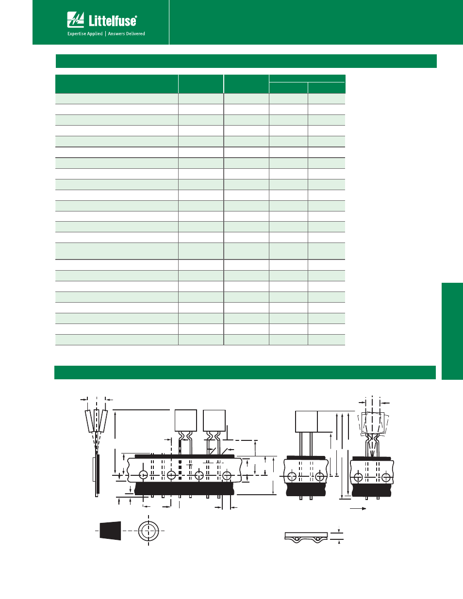
Tape and Ammo Specifications
Devices taped using EIA468-B/IE286-2 standards. See table below and Figure 1 for details.
Tape and Ammo Diagram
A
B
A
1
L
1
P
0
D
0
F
L
W
4
H
0
I
2
H
1
W
5
W
Reference plane
Δh
Δh
H
1
H
C
1
C
2
Δh
Δp
Direction of unreeling
Cross section A - B
t
Figure 1