Sidactor, Protection thyristors, Slic protection – Littelfuse Fixed Voltage Single Port Series MS-012 User Manual
Page 2: Fix ed v oltage single
102
SIDACtor
®
Protection Thyristors
© 2009 Littelfuse, Inc.
Specifications are subject to change without notice.
Please refer to www.littelfuse.com for current information.
SLIC Protection
Fix
ed V
oltage
Single
Package
Symbol
Parameter
Value
Unit
1
2
3
4
8
7
6
5
MS-012
T
J
Operating Junction Temperature Range
UP
°C
T
S
Storage Temperature Range
UP
°C
R
0JA
Thermal Resistance: Junction to Ambient
120
°C/W
Series
I
PP
I
TSM
di/dt
2x10μs
1.2x50μs/8x20μs
10x700/5x310μs
10x1000μs
600V
RMS
1s
A min
A min
A min
A min
A min
Amps/μs max
F
120
100
50
30
1
500
Surge Ratings
Thermal Considerations
Note: Off-state capacitance (C
O
) is measured at 1 MHz with a 2 V bias.
Capacitance Values
Part Number
pF
Pin 1,8-6,7 / 4,5-6,7
Tip-Ground, Ring-Ground
pF
Pin 1,8-4,5
Tip-Ring
MIN
MAX
MIN
MAX
P0641DF-1
40
90
20
45
P0721DF-1
35
85
20
45
P0901DF-1
30
80
20
40
P1001DF-1
25
75
15
35
P1101DF-1
25
70
15
30
50
100
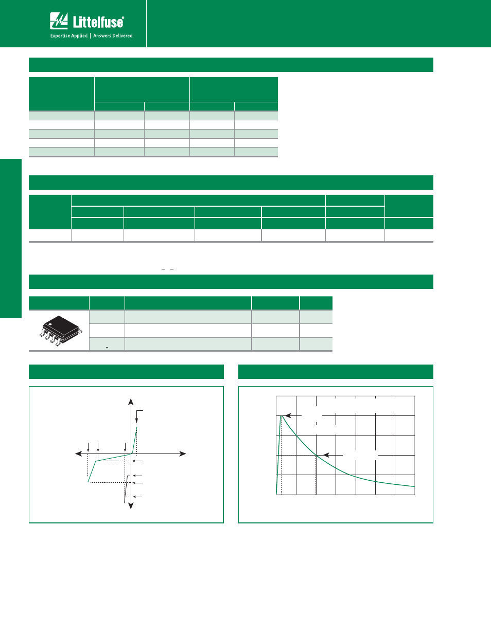
0
t
r
t
d
0
Peak
Value
Half Value
t – Time (μs)
I
PP
– P
eak Pulse Current – %I
PP
t
r
= rise time to peak value
t
d
= decay time to half value
Waveform = t
r
x t
d
V-I Characteristics
t
r
x t
d
Pulse Waveform
I
H
I
DRM
V
DRM
V
T
+V
+I
V
S
I
S
I
T
V
F
-V
-I
Notes:
- Peak pulse current rating (I
PP
) is repetitive and guaranteed for the life of the product.
- I
PP
SBUJOHTBQQMJDBCMFPWFSUFNQFSBUVSFSBOHFPG$UP$
- The device must initially be in thermal equilibrium with -40°C < T
J
<
¡$