Littelfuse 30R Series User Manual
Polyfuse, Resettable ptcs, 30r series
75
Revised: July 12, 2010
POLYFUSE
®
Resettable PTCs
© 2010 Littelfuse, Inc
30R Series
Radial Leaded > 30R Series
Specifications are subject to change without notice.
Please refer to www.littelfuse.com/series/30R.html for current information.
30R S
eries
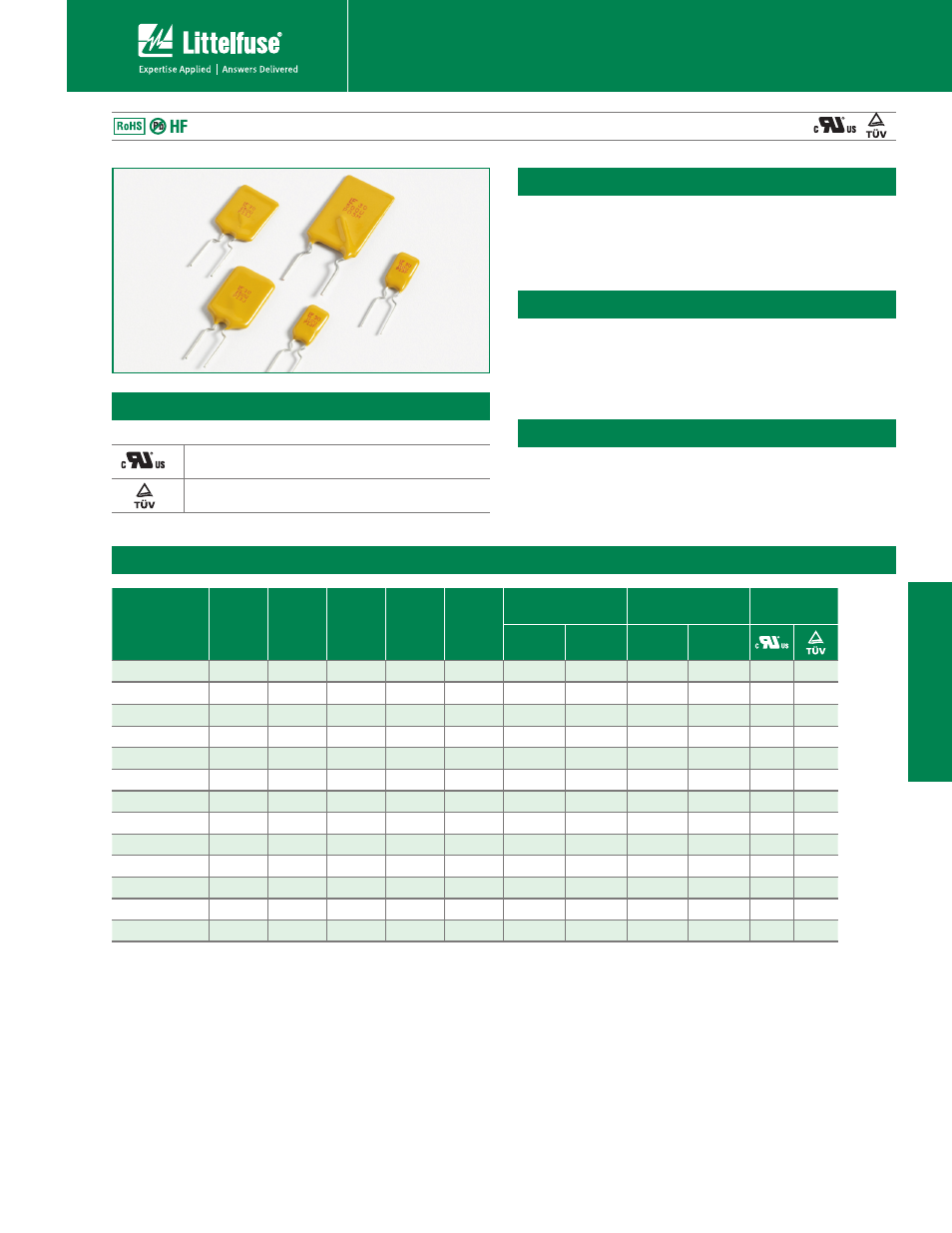
30R Series
t5IF34FSJFTSBEJBMMFBEFEEFWJDFJTEFTJHOFEUP
provide overcurrent protection for low voltage (≤30V)
applications where space is not a concern and resettable
protection is preferred.
Electrical Characteristics
Part Number
I
hold
(A)
I
trip
(A)
V
max
(Vdc)
I
max
(A)
P
d
typ.
(W)
Maximum Time
To Trip
Resistance
Agency
Approvals
Current
(A)
Time
(Sec.)
R
min
(Ω)
R
1max
(Ω)
30R090
0.90
1.80
30
40
0.6
4.50
5.90
0.070
0.220
X
X
30R110
1.10
2.20
30
40
0.7
5.50
6.60
0.050
0.170
X
X
30R135
1.35
2.70
30
40
0.8
6.75
7.30
0.040
0.130
X
X
30R160
1.60
3.20
30
40
0.9
8.00
8.00
0.030
0.110
X
X
30R185
1.85
3.70
30
40
1.0
9.25
8.70
0.030
0.090
X
X
30R250
2.50
5.00
30
40
1.2
12.50
10.30
0.020
0.070
X
X
30R300
3.00
6.00
30
40
2.0
15.00
10.80
0.020
0.080
X
X
30R400
4.00
8.00
30
40
2.5
20.00
12.70
0.010
0.050
X
X
30R500
5.00
10.00
30
40
3.0
25.00
14.50
0.010
0.050
X
X
30R600
6.00
12.00
30
40
3.5
30.00
16.00
0.005
0.040
X
X
30R700
7.00
14.00
30
40
3.8
35.00
17.50
0.005
0.030
X
X
30R800
8.00
16.00
30
40
4.0
40.00
18.80
0.005
0.020
X
X
30R900
9.00
18.00
30
40
4.2
40.00
20.00
0.005
0.020
X
X
Description
Features
Applications
t$VSFE nBNFSFUBSEBOU
epoxy polymer insulating
material meets UL 94V-0
requirements
t'BTUUJNFoUPUSJQ
t3P)4DPNQMJBOU
-FBE
Free and Halogen-Free*
t64#IVCT QPSUT
and peripherals
t$PNQVUFSTQFSJQIFSBMT
t.PUPSQSPUFDUJPO
t(FOFSBMFMFDUSPOJDT
t"VUPNPUJWFBQQMJDBUJPOT
I
hold
= Hold current: maximum current device will pass without tripping in 23°C still air.
I
trip
= Trip current: minimum current at which the device will trip in 23°C still air.
V
max
= Maximum voltage device can withstand without damage at rated current (I
max
)
I
max
= Maximum fault current device can withstand without damage at rated voltage (V
max
)
P
d
= Power dissipated from device when in the tripped state at 23°C still air.
R
min
= Minimum resistance of device in initial (un-soldered) state.
R
1max
= Maximum resistance of device at 23°C measured one hour after tripping.
Caution: Operation beyond the specified rating may result in damage and possible arcing
and flame.
Agency Approvals
AGENCY
AGENCY FILE NUMBER
E183209
R50119318
* Effective January 1, 2010, all 30R PTC products will be manufactured Halogen Free (HF). Existing Non-Halogen Free 30R PTC products may continue to be sold, until supplies are depleted.