Teccor, Brand thyristors, 25 amp high temperature alternistor triacs – Littelfuse HQ6025xH5 Series User Manual
Page 3
145
Revised: 09/23/13
©2013 Littelfuse, Inc
Specifications are subject to change without notice.
Teccor
®
brand Thyristors
25 Amp High Temperature Alternistor Triacs
HQ6025xH5 Series
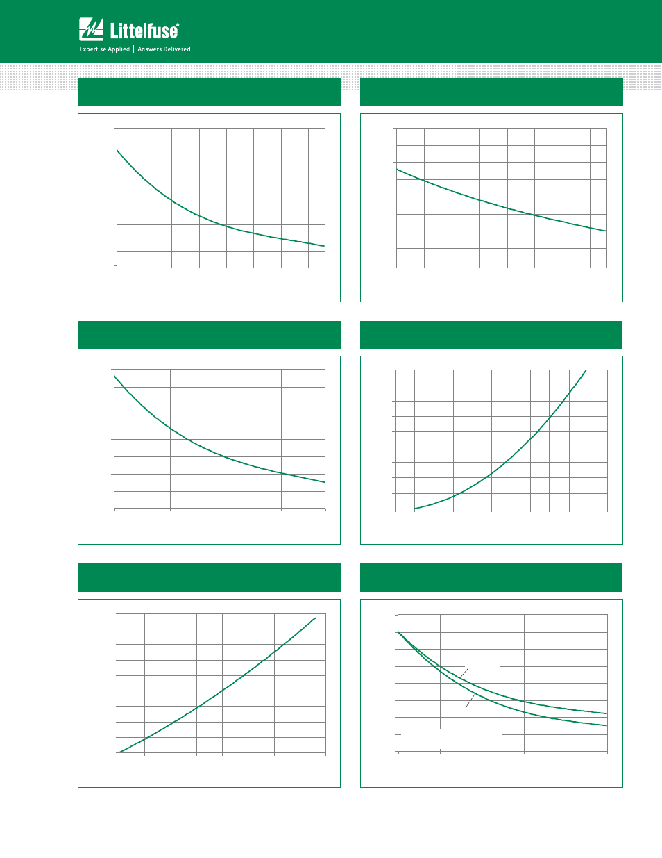
Figure 1: Normalized DC Gate Trigger Current
vs. Junction Temperature
Figure 2: Normalized DC Gate Trigger Voltage
vs. Junction Temperature
0.0
0.5
1.0
1.5
2.0
-40
-15
10
35
60
85
110
135
Junction Temperature (T
J
) -- (°C)
Ratio of
V
GT
/ V
GT
(T
J
= 2
5
°C)
150
0.0
0.5
1.0
1.5
2.0
2.5
-40
-15
10
35
60
85
110
135
150
Junction Temperature (T
J
) -- (°C)
Ratio of I
GT
/ I
GT
(T
J
= 2
5
°C)
Figure 3: Normalized DC Holding Current
vs. Junction Temperature
Figure 4: On-State Current vs. On-State
Voltage (Typical)
0.0
0.5
1.0
1.5
2.0
-40
-15
10
35
60
85
110
135
Junction Temperature (T
J
) -- (°C)
Ratio of I
H
/ I
H
(T
J
= 2
5
°C)
150
0
10
20
30
40
50
60
70
80
90
0.7
0.8
0.9
1.0
1.1
1.2
1.3
1.4
1.5
1.6
1.7
1.8
Instantaneous On-state Voltage (v
T
) – Volts
Instantaneous On-stat
e Cur
rent (i
T
) –
Amps
Figure 5: Power Dissipation (Typical) vs. RMS
On-State Current
Figure 6: Maximum Allowable Case Temperature
vs. RMS On-State Current
0
5
10
15
20
25
30
35
40
45
0
5
10
15
20
25
30
35
40
RMS On-State Current [I
T(RMS)
] -- Amps
A
v
er
ag
e On-Stat
e P
o
w
e
r Dissipation
[P
D(A
V)
] --
W
a
tt
s
80
90
100
110
120
130
140
150
160
0
5
10
15
20
25
RMS On-State Current [I
T(RMS)
] - Amps
Maximum
Allo
w
able Case
Temper
at
ur
e (T
C
) - °C
HQ6025LH5
HQ6025RH5
HQ6025NH5
HQ6025KH5
CURRENT WAVEFORM: Sinusoidal
LOAD: Resistive or Inductive
CONDUCTION ANGLE: 360°