Thermal considerations, V-i characteristics, Vbr vs. junction temperature – Littelfuse PLEDxSW Series User Manual
Page 2: Normalized dc holding current vs. case temperature, Led interference test circuit, Pled open led protectors, Pledxsw series
2
PLED Open LED Protectors
Revision: May 23, 2013
©2013 Littelfuse, Inc.
Specifications are subject to change without notice.
Please refer to
www.littelfuse.com
for current information.
PLEDxSW Series
PLEDxSW Series
Package
Symbol
Parameter
Value
Unit
T
J
Operating Junction Temperature Range
-40 to +150
°C
T
S
Storage Temperature Range
-65 to +150
°C
R
θJA
Thermal Resistance: Junction to Ambient
DO-214AA: 90
1
DO-214AA: 40
2
°C/W
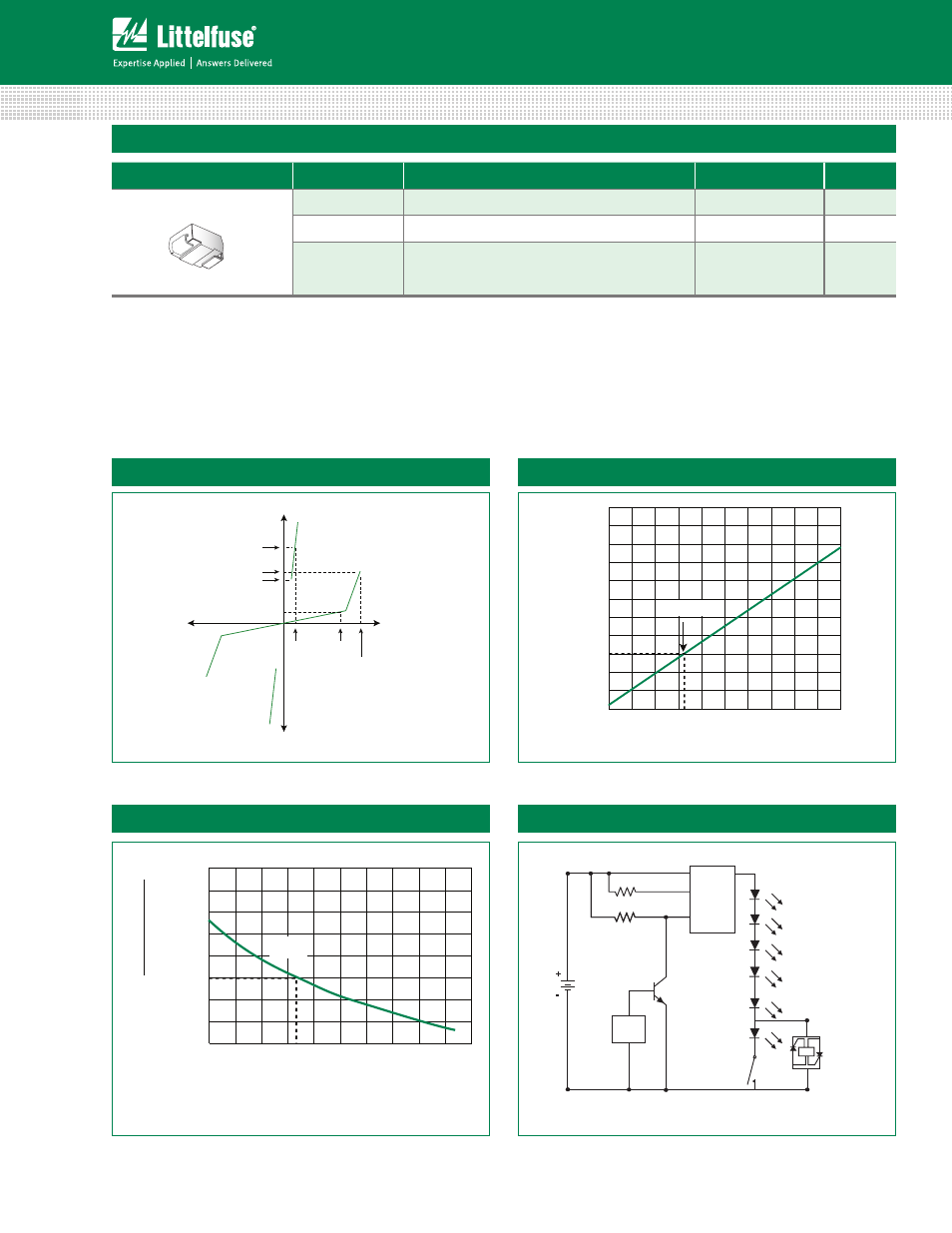
Thermal Considerations
I
H
I
T
I
S
V
DRM
V
T
+V
-V
+I
-I
V
BR
V-I Characteristics
0.4
-40 -20
0.6
0.8
1.0
1.2
1.4
1.6
1.8
2.0
Case Temperature (T
C
) – ˚C
fo
oit
a
R
i
H
i
H
T(
C
C˚
52
=)
25 ˚C
0 20 40 60 80 100 120 140 160
ON/OFF
Switch
PWM
LED
Driver
V
bat
12 Vdc
+
-
2.0
Ω, 1/4 W
110 k
Ω, 1/4 W
Q2
2N2222
Q1
PLED
Control
Circuit
-8
-40 -20
-6
-4
0
2
4
6
8
10
12
14
Junction Temperature (T
J
) – ˚C
re
P
fo
tn
ecV
BR
–
eg
na
h
C%
25 ˚C
0 20 40 60 80 100 120 140 160
V
BR
vs. Junction Temperature
Normalized DC Holding Current vs. Case Temperature
LED Interference Test Circuit
Notes:
1) Standard FR-4 PCB with Copper Pads (Recommended Size)
2) Aluminum PCB
Thickness: 1.6mm
Grade: 1-2 W/mK Thermal Conductivity
Trace thickness: 2 oz
Insulation layer thickness: 215 um
Solder Pad Dimensions: 2.0mm x 2.8mm (Recommended Size)
DO-214AA in White