Transient voltage suppression diodes, Tvs diode arrays, Surface mount > 3.0smc series – Littelfuse 3.0SMC Series User Manual
Page 2: Family of products)
Transient Voltage Suppression Diodes
© 2014 Littelfuse, Inc.
Specifications are subject to change without notice.
Revised: 01/24/14
Surface Mount > 3.0SMC Series
TVS Diode Arrays
(SPA
™
Family of Products)
Electrical Characteristics
(T
A
=25°C unless otherwise noted)
Part
Number
(Uni)
Marking
Reverse
Stand off
Voltage V
R
(Volts)
Breakdown
Voltage V
BR
(Volts) @ I
T
Test
Current
I
T
(mA)
Maximum
Clamping
Voltage V
C
@
8/20
µS
I
pp
(V)
Maximum
Peak Pulse
Current I
pp
@
8/20
µS
(A)
Maximum
Reverse
Leakage I
R
@ V
R
(µA)
MIN
MAX
3.0SMC20A
YLA
20.0
22.20
24.50
1
42
740
1
3.0SMC24A
YLC
24.0
26.70
29.50
1
51
520
1
3.0SMC28A
YLE
28.0
31.10
34.40
1
59
470
1
3.0SMC30A
YLF
30.0
33.30
36.80
1
62
420
1
3.0SMC33A
YLG
33.0
36.70
40.60
1
70
365
1
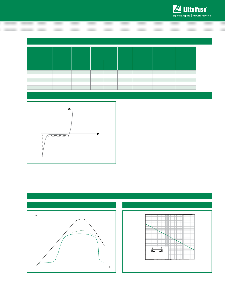
I-V Curve Characteristics
Voltage Transients
Time
Voltage Across TVS
Current Through TVS
Voltage or Current
Figure 1 - TVS Transients Clamping Waveform
Ratings and Characteristic Curves
(T
A
=25°C unless otherwise noted)
Figure 2 - Peak Pulse Power Rating
0.1
1
10
100
1000
0.001
0.01
0.1
1
P
PPM
-Peak Pulse Power (KW
)
10
0.31x0.31" (8.0x8.0mm)
Copper Pad Area
t
d
-Pulse Width (ms)
Vc V
BR
V
R
I
R
I
T
I
pp
V
Uni-directional
V
F
P
PPM
Peak Pulse Power Dissipation -- Max power dissipation
V
R
Stand-off Voltage -- Maximum voltage that can be applied to the TVS without operation
V
BR
Breakdown Voltage -- Maximum voltage that flows though the TVS at a specified test current (I
T
)
V
C
Clamping Voltage -- Peak voltage measured across the suppressor at a specified Ippm (peak impulse current)
I
R
Reverse Leakage Current -- Current measured at V
R
V
F
Forward Voltage Drop for Uni-directional
continues on next page.