Transient voltage suppression diodes, Tvs diode arrays, Surface mount – 600w > tpsma6l series – Littelfuse TPSMA6L Series User Manual
Page 3: Family of products), I-v curve characteristics, Figure 2 - peak pulse power rating curve
©2012 Littelfuse, Inc.
Specifications are subject to change without notice.
Transient Voltage Suppression Diodes
3
Revised: December 12, 2012
TVS Diode Arrays
(SPA
™
Family of Products)
TPSMA6L Series
Surface Mount – 600W > TPSMA6L Series
Please refer to http://www.Littelfuse.com for current information.
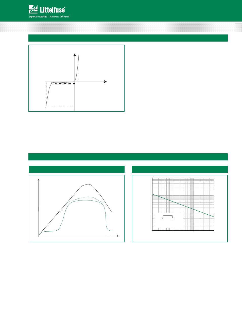
I-V Curve Characteristics
Vc V
BR
V
R
I
R
I
T
I
pp
V
Uni-directional
V
F
P
PPM
Peak Pulse Power Dissipation -- Max power dissipation
V
R
Stand-off Voltage -- Maximum voltage that can be applied to the TVS without operation
V
BR
Breakdown Voltage -- Maximum current that flows though the TVS at a specified test current (I
T
)
V
C
Clamping Voltage -- Peak voltage measured across the suppressor at a specified Ippm (peak impulse current)
I
R
Reverse Leakage Current -- Current measured at V
R
V
F
Forward Voltage Drop for Uni-directional
0.1
1
10
100
0.000001
0.00001
0.0001
0.001
t
d
-Pulse Width (sec.)
0.2x0.2" (5.0x5.0mm)
Copper Pad Area
P
PPM
-Peak Pulse Power (kW)
Figure 2 - Peak Pulse Power Rating Curve
Voltage Transients
Time
Voltage Across TVS
Current Through TVS
Voltage or Current
Figure 1 - TVS Transients Clamping Waveform
Ratings and Characteristic Curves
(T
A
=25°C unless otherwise noted)
continues on next page.