Varistor products, Radial lead varistors > tmov, And itmov – Littelfuse iTMOV Varistor Series User Manual
Page 3: Series, Tmov, It mov, Thermal characteristics, Current, energy, power derating curve, Tmov and itmov, Ratings & specifications
© 2013 Littelfuse, Inc.
209
Revised: October 21, 2013
Varistor Products
TMOV
®
and i TMOV
®
Varistor Series
Radial Lead Varistors > TMOV
®
and iTMOV
®
Series
Specifications are subject to change without notice.
Please refer to www.littelfuse.com/series/tmov.html for current information.
TMOV
®
/iT
MOV
®
S
eries
Note : The TMOV
®
and iTMOV
®
varistors are intended, in
conjunction with appropriate enclosure design, to help facilitate
SPD module compliance to UL 1449, 3rd Edition Section 39.4
(abnormal overvoltage limited current requirements). Under these
extreme abnormal overvoltage conditions, some units will exhibit
substantial heating, arcing and venting prior to opening. Modules
should be designed to contain this possibility. Application testing is
strongly recommended.
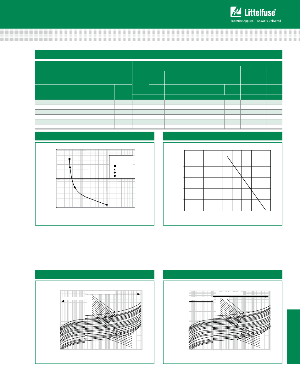
Thermal Characteristics
* Figure 4: Typical time to open circuit under UL1449
Abnormal Overvoltage Limited Current Test
0.1
1
10
10
100
1000
10000
Time(s)
0.125A
0.5A
2.5A
5A
Typical
For applications exceeding 85˚C ambient
temperature, the peak surge current and energy
ratings must be reduced as shown in Figure 5.
Figure 5: Peak Current & Energy Derating Curve
0
20
40
60
80
100
-55
50
60
70
80
90
100
110
120
130
AMBIENT TEMPERATURE (ºC)
PERCENT OF RATED VALU
E
Current, Energy, Power Derating Curve
100
1000
10000
0.000001 0.00001 0.0001 0.001 0.01
0.1
1
10
100
1000 10000
Peak Current (A)
Clamping
Vo
ltage (V)
175V
150V
140V
130V
320V
300V
275V
250V
230V
Figure 6: V-I Characteristic Curves for 14mm Types
420V
385V
115V
Maximum Leakage Current
Maximum Clamping Voltage
14mm
200V
460V
510V
550V
575V
625V
750V
Maximum Clamping Voltage for 14mm Parts
Maximum Clamping Voltage for 20mm Parts
100
1000
10000
0.000001 0.00001 0.0001 0.001 0.01
0.1
1
10
100
1000 10000
Peak Current (A)
Clamping Voltage (V
)
175V
150V
140V
130V
320V
275V
250V
230V
Figure 7: V-I Characteristic Curves for 20mm Types
420V
385V
115V
Maximum Leakage Current
Maximum Clamping Voltage
20mm
200V
460V
510V
550V
575V
625V
750V
300V
For applications exceeding 85°C ambient temperature, the peak
surge current and energy ratings must be reduced as shown
above.
Figure 1
Figure 2
Figure 3
Figure 4
TMOV and iTMOV
®
Ratings & Specifications
TMOV
Lead–free And RoHS
Compliant Models
iTMOV
Lead–free and RoHS
Compliant Models
Disc
Diameter
Maximum Rating (85°C)
Specifications (25°C)
Continuous
Transient
Varistor Voltage
at 1mA Test
Current
Maximum
Clamping
Voltage 8/20
µs
Typical
Capaci-
tance
f = 1MHz
AC
Volts
DC
Volts
Energy
2ms
Peak Surge
Current 8/20
µs
Part
Number
Branding
Part
Number
Branding
V
M(AC)RMS
V
M(DC)
W
TM
I
TM
1 ×
Pulse
I
TM
2 ×
Pulse
V
N(DC)
Min
V
N(DC)
Max V
C
I
PK
C
(mm)
(V)
(V)
(J)
(A)
(A)
(V)
(V)
(A)
(pF)
TMOV14RP575E P4T575E TMOV14RP575M P4T575M
14
575
730
195
6000
4500
856
1047
1568
50
170
TMOV20RP575E P2T575E TMOV20RP575M P2T575M
20
575
730
375
10000
6500
856
1047
1568
100
275
TMOV14RP625E P4T625E TMOV14RP625M P4T625M
14
625
825
200
6000
4500
900
1100
1650
50
160
TMOV20RP625E P2T625E TMOV20RP625M P2T625M
20
625
825
400
10000
6500
900
1100
1650
100
250
TMOV14RP750E P4T750E TMOV14RP750M P4T750M
14
750
970
210
6000
4500 1080
1320
1980
50
140
TMOV20RP750E P2T750E TMOV20RP750M P2T750M
20
750
970
480
10000
6500 1080
1320
1980
100
175