Sidactor, Protection thyristors, Broadband optimized – Littelfuse Q2L Series 3.3x3.3 QFN User Manual
Page 3: Protection
SIDACtor
®
Protection Thyristors
Revised: January 7, 2013
© 2013 Littelfuse, Inc.
Specifications are subject to change without notice.
Please refer to www.littelfuse.com for current information.
Broadband Optimized
™
Protection
Q2L Series - 3.3x3.3 QFN
Dimensions
Inches
Millimeters
Min
Max
Min
Max
"
0.126
0.134
3.200
3.400
#
0.126
0.134
3.200
3.400
C
0.075
0.083
1.900
2.100
E
0.011
0.019
0.285
0.485
F
0.088
0.096
2.230
2.430
H
0.035
0.043
0.900
1.100
J
0.000
0.008
0.000
0.200
,
0.004
0.012
0.100
0.300
,
0.004
0.012
0.100
0.300
M1
0.063
0.071
1.610
1.810
M2
0.045
0.053
1.153
1.353
N1
0.095
0.103
2.420
2.620
N2
0.082
0.090
2.080
2.280
2.54
(.100”)
H
1.50
(.059”)
1.27
(.050”)
K1
N2
N1
END VIEW
SIDE VIEW
M2
M1
K2
F
E
C
J
B
A
TOP VIEW
BOTTOM VIEW
Recommended
Soldering Pad Outline
(Reference Only)
Dimensions — 3.3x3.3 QFN
Soldering Parameters
Physical Specifications
Environmental Specifications
Lead Material
$PQQFS"MMPZ
Terminal Finish
.BUUF5JO1MBUFE
Body Material
6-SFDPHOJ[FEFQPYZNFFUJOHnBNNBCJMJUZ
DMBTTJmDBUJPO7
High Temp Voltage
Blocking
3BUFE7
DRM
(V
"$
1FBL
¡$PS¡$
PSIST.*-45% .FUIPE
+&%&$
+&4%"
Temp Cycling
¡$UP¡$
NJOEXFMM
VQUP
DZDMFT.*-45% .FUIPE&*"+&%&$
+&4%"
Biased Temp &
Humidity
52 V
DC
¡$3) VQUPIST&*"
+&%&$ +&4%"
High Temp Storage
¡$IST.*-45% .FUIPE
+&%&$
+&4%"
Low Temp Storage
¡$ IST
Thermal Shock
¡$UP¡$
NJOEXFMM
TFDUSBOTGFS
DZDMFT.*-45% .FUIPE+&%&$
+&4%"
Resistance to Solder
Heat
¡$ TFDT.*-45% .FUIPE
Moisture Sensitivity
Level
3)
¡$
IST
SFnPXDZDMFT
¡$1FBL+&%&$+45%
-FWFM
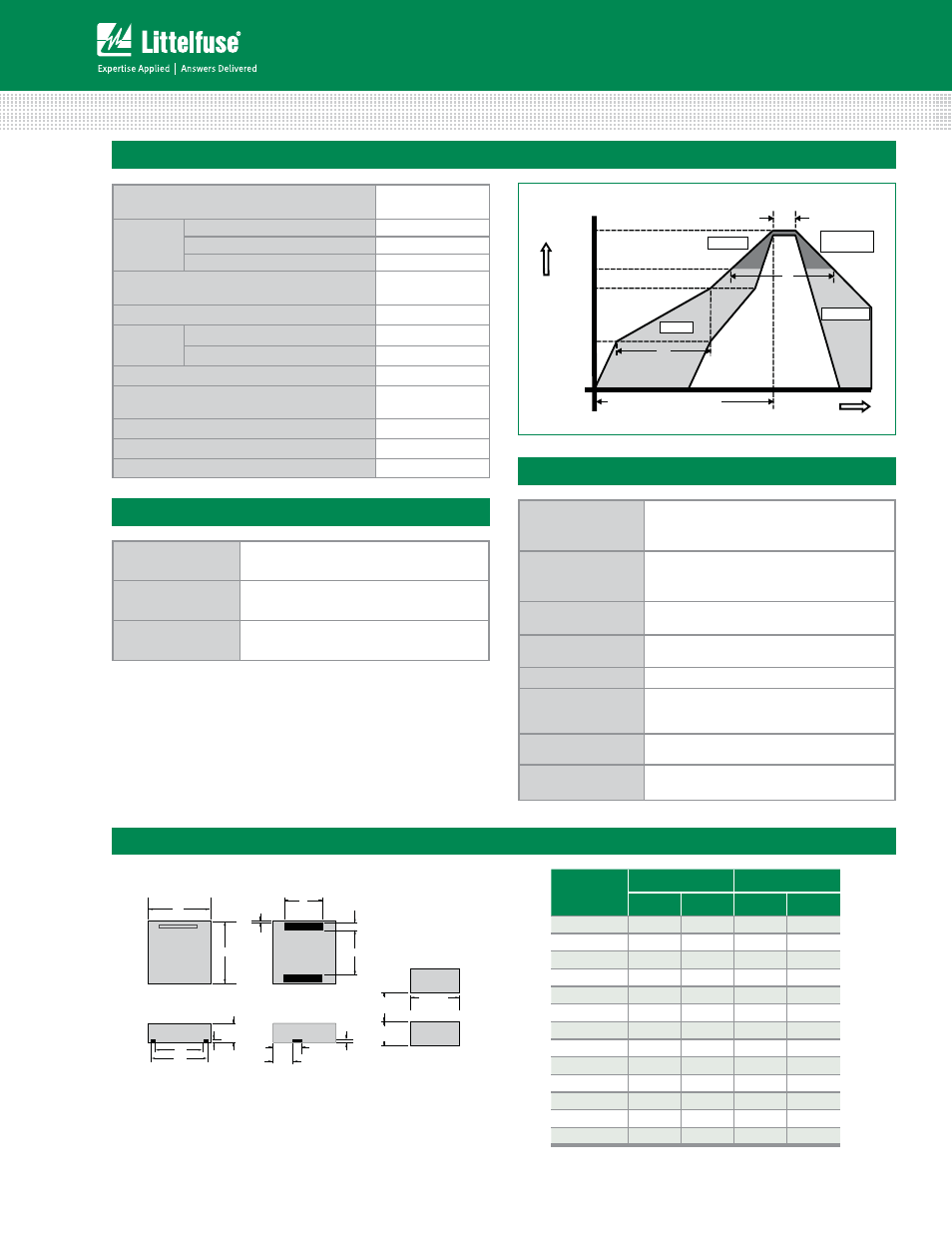
Reflow Condition
1C'SFFBTTFNCMZ
TFF'JH
Pre Heat
- Temperature Min (T
s(min)
)
¡$
- Temperature Max (T
s(max)
)
¡$
- Time (Min to Max) (t
s
)
TFDT
Average ramp up rate (Liquidus Temp (T
L
)
to peak)
¡$TFD.BY
T
S(max)
to T
L
- Ramp-up Rate
¡$TFD.BY
Reflow
- Temperature (T
L
) (Liquidus)
¡$
- Temperature (t
L
)
TFDT
Peak Temp (T
P
)
¡$
Time within 5°C of actual Peak Temp (t
p
)
TFDT.BY
Ramp-down Rate
¡$TFD.BY
Time 25°C to Peak Temp (T
P
)
NJO.BY
Do not exceed
¡$
Time
T
emper
at
ur
e
T
P
T
L
T
S(max)
T
S(min)
25
t
P
t
L
t
S
time to peak temperature
(t 25ºC to peak)
Ramp-down
Ramp-up
Preheat
Critical Zone
T
L
to T
P
Figure 1