Setup input panel, Operation manual page 14 page 15 operation manual – Crown Audio VRack4X3500HD User Manual
Page 8
Operation Manual
page 14
page 15
Operation Manual
Choose Input Wire and Connectors
Crown recommends using pre-built or professionally wired, balanced line (two-conductor plus shield), 22-24 gauge cables
with 3-pin XLR connectors. Unbalanced line may also be used but may result in noise over long cable runs.
Figure 1 shows connector pin assignments for balanced analog wiring or AES/EBU digital wiring. (The use of standard
analog cable with AES/EBU will result in diminished performance) For best results, 110 ohm shielded twisted-pair
cable for AES/EBU signals is highly recommended. Figure 2 shows connector pin assignments for unbalanced analog wiring.
NOTE: Custom wiring should only be performed by qualified personnel.
Choose Output Wire and Connectors
Crown recommends using pre-built or professionally wired, high-quality, two-, four- or eight-conductor, heavy gauge speaker
wire and connectors. Use Class 2 output wiring. You may use a 4- or 8-pole Speakon
®
connector. To prevent the possibility of
short circuits, wrap or otherwise insulate exposed loudspeaker cable connectors.
CAUTION – SHOCK HAZARD: Potentially lethal voltages exist at the output connectors when the amplifier is
turned on and is passing a signal.
Using the guidelines below, select the appropriate size of wire based on the distance from amplifier to speaker.
Distance
Wire Size
up to 25 ft. (up to 7.62 m)
16 AWG
26-40 ft. (7.62-12.2 m)
14 AWG
41-60 ft. (12.2-18.3 m)
12 AWG
61-100 ft. (18.3-30.5 m)
10 AWG
101-150 ft. (30.5-45.7 m)
8 AWG
151-250 ft. (45.7-76.2 m)
6 AWG
CAUTION: Never use shielded cable for output wiring.
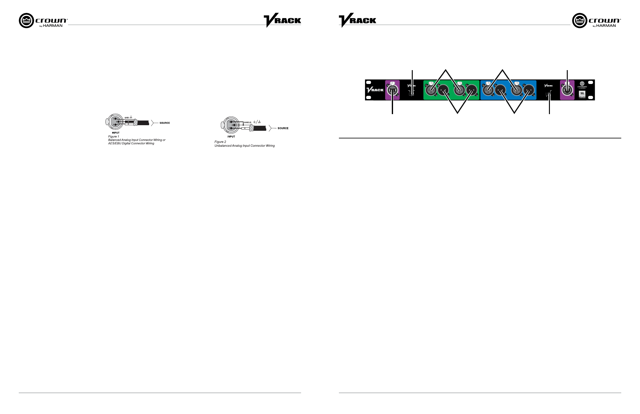
Setup
Input Panel
NETWORK
AES 1+2
AES 3+4
ANALOG 1
ANALOG 2
IN
NETWORK
OUT
AES XLR
to VDrive
On-Amp
No VDrive
or AES to
Amps
VDrive through
Ethernet In Only
Send to
Network
Output
OFF
IN
OUT
IN
OUT
IN
OUT
IN
OUT
A
G
D
F
B
H
C
E
A. Network Link input. Also distributes VDrive Digital Audio.
B. VDrive Input Switch:
AES XLR to VDrive On-Ramp - When the switch is in this position, the AES3 signal
that is connected to AES 1+2 or AES 3+4 XLR is buffered then sent to the amplifiers via
VDrive and also buffered and sent to the Network Link Out.
VDrive through Ethernet only - When the switch is in this position, the VDrive signal
present on the Network Link Input is buffered and sent to the amplifiers via VDrive and
also buffered and sent to the Network Link Out.
No VDrive or AES to Amps - When the switch is in this position, no AES3 signal is
distributed from the input panel to the amplifiers. This mode should be used when
patching AES3 signal directly to the amplifiers when the input panel is bypassed.
C. AES3 Inputs - Sends AES3 signal to the amplifiers. When VDrive switch is set to
"AES XLR to VDrive On-Ramp" this input AES3 signal is sent to the 3 amplifiers with
the VRack and sent to Network out VDrive.
D. AES3 Link Outputs - When power is applied to the rack, the AES3 signal is taken
from the input, buffered, then sent to this link output connection. If the rack is not
powered on, AES3 signal is still sent from the input connection but it is not buffered.
E. Analog Inputs - Analog 1 of this input panel is sent to each IT4x3500HD's analog 1
input. Analog 2 of this input panel is sent to each IT4x3500HD's Analog 3 input. This is
set up this way so that when the rack is configured to bi-amp mode, the amplifiers see
Analog 1 and 3 inputs.
F. Analog outputs - These outputs are in parallel with the analog inputs. There are no
active or passive circuitry between the input and output connections.
G. VDrive Output Switch - This switch selects whether or not the buffered AES3 Signal
based on the VDrive input switch selection is sent out the Network Link Output. When
in "OFF" Mode, network communication is still maintained regardless of the switch
position.
H. Network Link Output - Also distributes VDrive digital audio if the VDrive Output
switch is enabled.
***NOTE – All AES 3 signals are sent from the input panel to the Amplifiers via VDrive. Therefore, any time you use the VRack's input panel
for AES3 distribution to the amplifiers, the IT4x3500HD amplifier must be set to VDrive AES mode. (See Page 16 for more information)