Setup, Operation manual page 8 page 9 operation manual – Crown Audio VRack4X3500HD User Manual
Page 5
Operation Manual
page 8
page 9
Operation Manual
Suspension Hardware Inspection & Maintenance
Suspension systems are comprised of mechanical devices and, as such, they require regular inspection and routine
maintenance to ensure proper function ability. The Crown VRack must be inspected for fatigue at least annually. The inspection
shall include a visual survey of all corners and load-bearing surfaces for signs of cracking, water damage, de-lamination, or
any other condition that may decrease the strength of the power amplifier rack enclosure. Accessory suspension hardware
provided with or for the Crown VRack must be inspected for fatigue at least annually. The inspection shall include a visual
material survey for signs of corrosion, bending or any other condition that may decrease strength of the fastener. For other
fittings used, refer to the manufacturer’s inspection and maintenance guidelines for process.
Crown is not responsible for the application of its products for any purpose or the misuse of this information for any purpose.
Furthermore, Crown is not responsible for the abuse of its products caused by avoiding compliance with inspection and
maintenance procedures or any other abuse. Prior to suspending the system, an expert trained and experienced in flying
loudspeaker and power amplifier systems should inspect all suspension parts and components.
Industry Resources
Allen Products
562-424-1100
1635 E. Burnett Street
Signal Hill, CA 90755
www.adapttechgroup.com
M.A.N. Flying Systems
20 Sidar Road Brook Road
Industrial Estate
Rayleight, Essex SS6 7XF U.K.
www.manfly.co.uk
McMaster Carr
Various locations throughout the U.S.A.
For a location near you, visit them online:
www.mcmastercarr.com
Safe Suspension
The Crown VRack is equipped with integral suspension hardware and should only be suspended using the supplied
equipment. The system is designed to facilitate the suspension of the VRacks by a qualified person familiar with suspension
hardware and industry practices. Improper installation may result in damage, injury or death.
Working Load Limit
The working load limit (WLL) for any group of VRack products is noted on the appropriate VRack Array Frame. If interested in
suspending your VRacks, contact your local Crown representative for information on ordering VRack Suspension Frame.
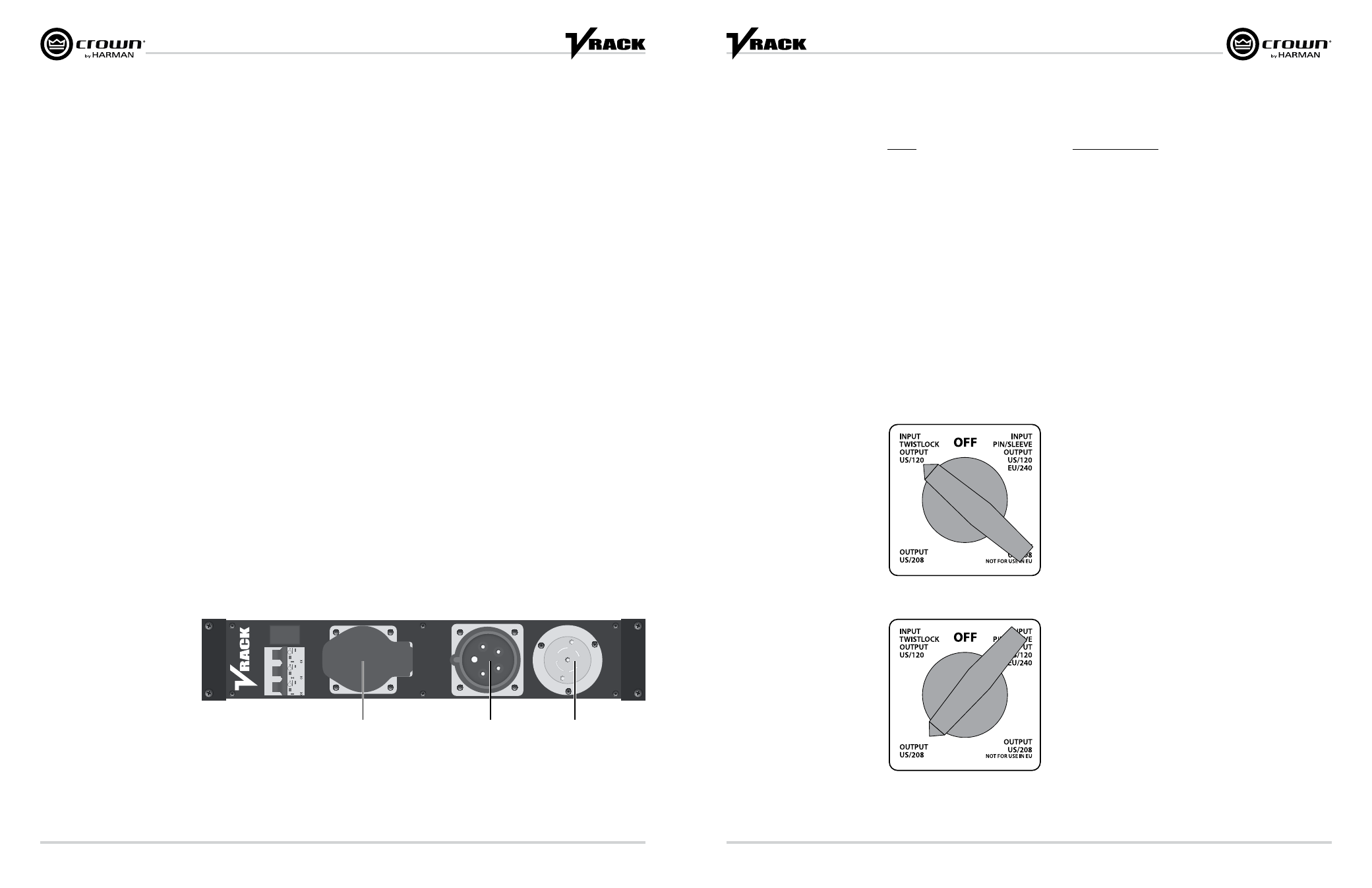
Setup
IEC 309
Pin + Sleeve style
Loop out
Walther 430
IEC 309
Pin + Sleeve style
Input
Walther 635
NEMA L21-30
Panel mount
Hbl2815
VRack Connectors
Setup
Type of Connectors to Use with VRack
L21-30
Mcaster-Carr
Female: 7184K35
Male: 7184K34
Hubbel Catalog
Female: HBL2813
Male: HBL2811
I
EC 309 Pin + Sleeve
Walther-Electric
Female: 330
Male: 230
Cooper Crouse-Hinds
Female: CH532C6W
Male: CH532P6W
VRack Power Distribution Overview
The VRack Power Distribution panel offers worldwide use capabilities as well as multiple AC operations when used with
120VAC input. This power distribution system allows 120VAC input to 120VAC output, 120VAC input to 208VAC output when
used with 3 phase power, 220VAC – 240VAC input to 220VAC – 240VAC output. It also features a 32A per circuit, 3-pole,
single-throw breaker as well as an LCD readout that indicates AC Voltage. Built-in +5V and +12V outputs power the VRack’s
built-in network switch and rear rack lighting features. Combine this worldwide capable power distro with the I-Tech HD’s
Universal, Power-Factor-Corrected Power Supply and the VRack can be used anywhere in the world.
Hubbell L21-30 U.S. Operation
Hubbell L21-30 12 120VAC Operation
Switch position “Input Twistlock, Output US/120” provides the user with 120V
operation to the I-Tech HD amplifiers in the rack. From an external power
distribution system, send 3 phase 120VAC power to the X, Y, and Z pin of the
Hubbell connector and the VRack will operate in 120V mode. Each I-Tech HD
amplifier will see a dedicated X, Y, or Z phase to the line input, neutral, and
Ground connection.
Amp 1 = X, Neutral, and GND
Amp 2 = Y, Neutral, and GND
Amp 3 = Z, Neutral, and GND
Hubbell L21-30 208VAC Operation
Switch Position “Input Twistlock, Output US/208” provides the user with
208VAC operation to the I-Tech HD amplifiers in the rack. From an external
power distribution system, send 3 phase 120VAC power to the X, Y, and Z
pin of the Hubbell connector and the VRack will operate in 208V mode. Each
I-Tech HD amplifier will see a dedicated line-to-line and ground connection
resulting in the VRack operating in 208VAC mode.
Amp 1 = X, Y, and GND
Amp 2 = Y, Z, and GND
Amp 3 = X, Z, and GND