Fi g. 7.1 – Peerless-AV WL-EPT650-200 - Installation User Manual
Page 11
11 of 16
ISSUED: 08-24-12 SHEET #: 180-9033-2 10-30-12
If you have any questions, please call Peerless customer care at 1-800-865-2112.
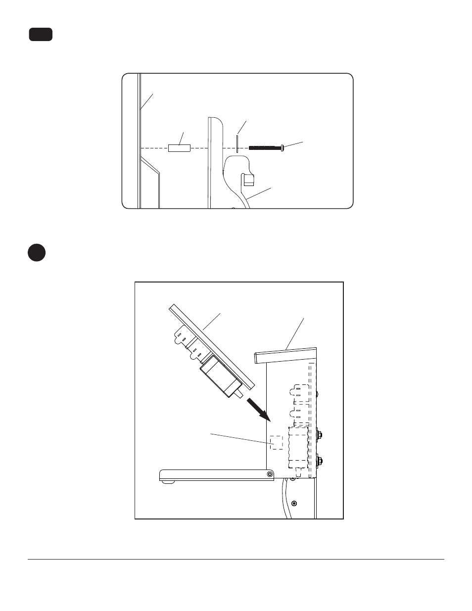
Begin with longer length screw, hand thread through multi-washer, tilt bracket and spacer in that order into display
as shown below. Screw must make at least three full turns into the mounting hole and fi t snug into place. Do not
over tighten. If screw cannot make three full turns into the display, select a longer length screw from the baffl ed
fastener pack. Repeat for remaining mounting holes, level brackets and tighten screws.
7-1
DISPLAY
MULTI-WASHER
SCREW
TILT BRACKET
(B or C)
fi g. 7.1
SPACER
FOAM PADS
Insert the sub panel assembly into the wireless receiver enclosure (G) above the foam pads as shown. Push the
sub panel assembly down and towards the rear of the until it makes contact with the back wall and the bottom of
the enclosure .
8
G
SUB PANEL
ASSEMBLY
- SF680P - Installation (20 pages)
- SFLT646 - Sell Sheet (2 pages)
- LCT620AD - Installation (9 pages)
- HLG440-LG-Q10 - Installation (8 pages)
- LCZ-4F4G30B - Installation (26 pages)
- PRMTLU - Sell Sheet (2 pages)
- STL646 - Sell Sheet (2 pages)
- DS-VW665 - Sell Sheet (2 pages)
- HG442-HT3-S - Installation (7 pages)
- PT660 - Sell Sheet (2 pages)
- SUA765PU - Sell Sheet (2 pages)
- SF670P - Installation (20 pages)
- HF642-003 - Installation (7 pages)
- DS509 - Sell Sheet (2 pages)
- ST632-AW - Installation (29 pages)
- SFL646 - Installation (20 pages)
- PP730 - Sell Sheet (2 pages)
- HT642-003 - Sell Sheet (2 pages)
- IWB600-UNIV - Installation (18 pages)
- HS432-001 - Installation (6 pages)
- SFL637 - Sell Sheet (2 pages)
- IM746P - Installation (24 pages)
- SF630-S - Sell Sheet (2 pages)
- SA761PU - Sell Sheet (2 pages)
- DST995 - Installation (13 pages)
- MIS343 - Installation (3 pages)
- FPEPM-08 - Installation (24 pages)
- ST630-AW - Installation (26 pages)
- DS-VW765-LAND - Installation (13 pages)
- HLG452-SM-Q10 - Sell Sheet (2 pages)
- LCZ-4F4G30B - Sell Sheet (2 pages)
- SF632-AW - Sell Sheet (2 pages)
- FPZ-655 - Sell Sheet (2 pages)
- SUA746PU - Installation (29 pages)
- HS432-002 - Installation (6 pages)
- ST16D - Installation (11 pages)
- LCC-36S - Sell Sheet (2 pages)
- PRMF2X2 - Sell Sheet (2 pages)
- SF632P - Installation (24 pages)
- SC560FK - Installation (11 pages)
- MOD-FPSKIT150-B - Sell Sheet (2 pages)
- SP746PU - Sell Sheet (2 pages)
- IWB600-2SB - Installation (13 pages)
- YBT2X1 - Sell Sheet (2 pages)
- FDS-3250 - Sell Sheet (2 pages)