PowerWalker ATS User Manual
Page 7
EN
Contact Ports
The contacts port is formed using six (6) pins numbered from left to right (see fig. 1), which can be
connected to an external monitoring system (such as a BMS) in order to monitor the operational
status of the ATS.
The external equipment must respect the voltage and current characteristics of contacts port.
Fig. 1: Focus on contacts port.
The contacts port provides the following pins:
Pin 1: common contact.
Pin 2: “Source B” active contact (if the contact between “pin 1” and “pin 2” is closed, output is
supplied by “Source B”).
Pin 3: “Source A” active contact (if the contact between “pin 3” and “pin 1” is closed, output is
supplied by “Source A”).
Pin 4: “Source A” status OK contact (if the contact between “pin 4” and “pin 1” is closed,
“Source A” is present and regular).
Pin 5: “Source B” status OK contact (if the contact between “pin 5” and “pin 1” is closed,
“Source B” is present and regular).
Pin 6: Status OK contact (if the contact between “pin 6” and “pin 1” is closed, ATS functioning
status is regular).
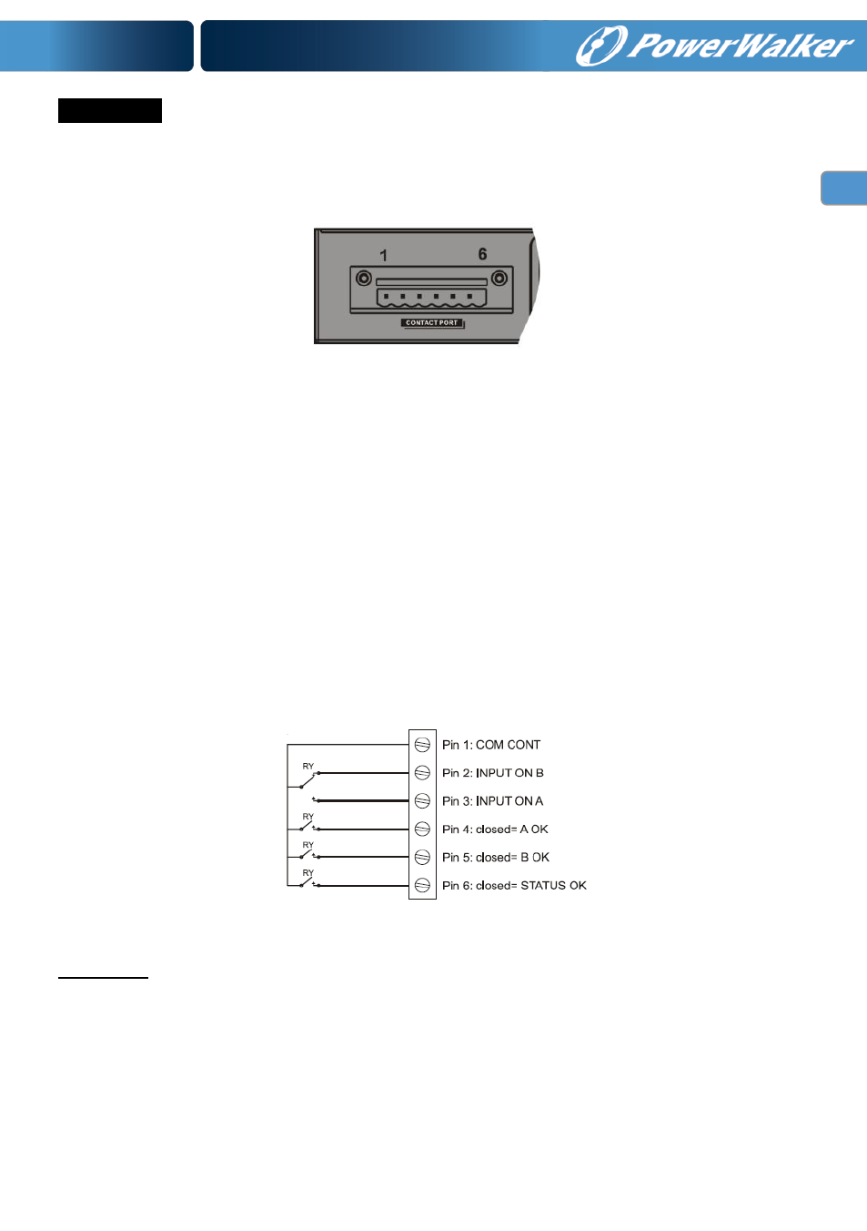
The following diagram shows the functioning of the contacts port.
Fig. 2: Contacts port basic diagram.
ATTENTION: The pins of the contact port are able to carry maximum current of 8A and maximum
voltage of 250Vac.