B&B Electronics GW-7552 - Quick Start Guide User Manual
Page 8
GW-7552 PROFIBUS/MODBUS GATEWAY Quick Start User Guide (Version 1.30) PAGE:8
area of Profibus master device and then set the value of the first byte from 0
to 1 to trigger the data output command.
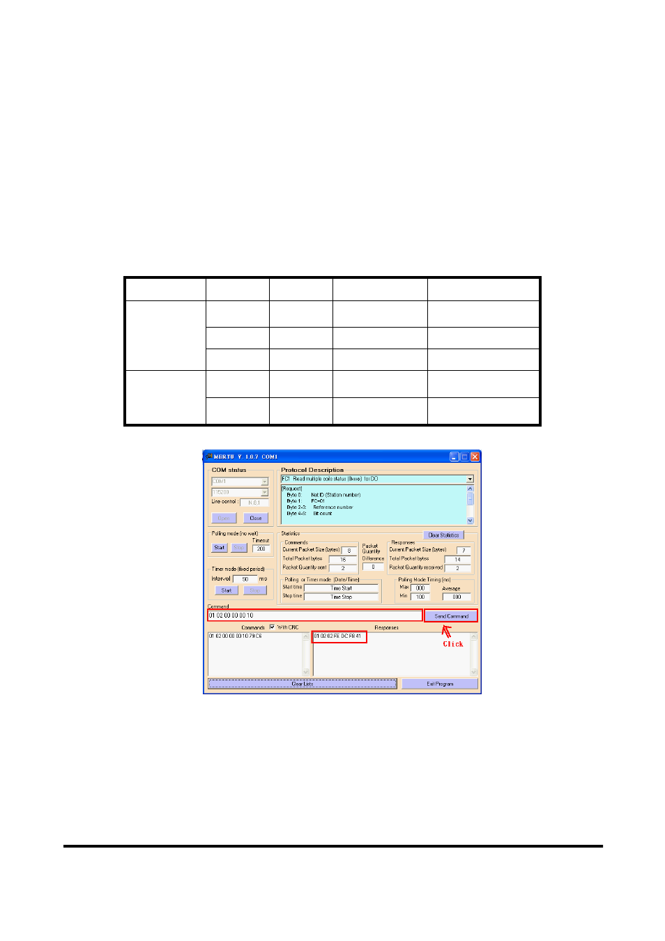
--Send Command to read DI of the GW-7552 again
Now the user can input command (” 01 02 00 00 00 10”) in MBRTU and
click
MBRTU can receive response message (” 01 02 02 FE DC F8 41”). In this
message, the user can know the value of DI0 & DI1 have changed into
“0xFE” & “0xDC” in the GW-7552, as shown in the below.
Set output data and trigger output data command
Module Byte
Data
type Representation
Value
Output 0
Byte
Hex
0x00
→
0x01
Output 1
Byte
Hex
0x00
System
module
Output 2
Byte
Hex
0x00
Output 3
Byte
Hex
0x00
→
0xFE
Output
module
Output 4
Byte
Hex
0x00
→
0xDC
Send Modbus command to read DI of the GW-7552 and receive data (0xFE, 0xDC)
- USOPTL4DR-LS - Datasheet (2 pages)
- ZXT9-IOA-KIT - Manual (75 pages)
- ADAM-6066 - Manual (272 pages)
- 855-11619--57 - Datasheet (2 pages)
- 851-10904 - Datasheet (2 pages)
- SS-BLT-100PR - Quick Start Guide (1 page)
- ISOCON-6 - Datasheet (2 pages)
- I-7060 - Manual (64 pages)
- AMU864 - Datasheet (2 pages)
- 714FX6-SC_ST - Manual (154 pages)
- 422LP25R - Datasheet (2 pages)
- ZP9D-115RM-LR - Manual (54 pages)
- EKI-6311GN-EU - Manual (56 pages)
- ZZ24D-NA(NB,NC,ND)-SR - Quick Start Guide (4 pages)
- ESCLP-100 - Manual (23 pages)
- 806-39753 - Datasheet (1 page)
- 485SD9RJ - Datasheet (1 page)
- 712FX4-SC_ST - Manual (154 pages)
- 850-18610 - Manual (18 pages)
- ESW208 Series - Datasheet (2 pages)
- VESR321_ML_SL - Quick Start Guide (3 pages)
- OP10 - Datasheet (1 page)
- RT3G-300_310_320_330_340-W - Configuration Manual (79 pages)
- EIRHP305-T - Datasheet (2 pages)
- EIRSP1 - Datasheet (1 page)
- 422TTL33 - Datasheet (2 pages)
- 485DRCI - Quick Start Guide (2 pages)
- I-7021_P - Datasheet (2 pages)
- NTSA-CAT5E - Datasheet (2 pages)
- 485COSR - Datasheet (2 pages)
- 855-10619--57 - Datasheet (2 pages)
- UH401SL_2KV - Datasheet (2 pages)
- 105FXE-SC(ST)-15-POE - Manual (19 pages)
- 102MC-FL_SC_ST - Manual (23 pages)
- CBL00302 - Datasheet (1 page)
- 850-18100--27 - Datasheet (2 pages)
- 850-10953-DC - Datasheet (2 pages)
- ESR904 - Datasheet (2 pages)
- 308TX-N - Datasheet (3 pages)
- 422LP25N - Datasheet (2 pages)
- 708FX2-SC_ST - Datasheet (3 pages)
- MESR321_SL_ML - Datasheet (2 pages)
- SL2736-698 - Quick Start Guide (8 pages)
- I-7188E Series - Datasheet (1 page)
- ANT-PAD58-19 - Datasheet (1 page)