B&B Electronics 855-12260--63 - Manual User Manual
Page 11
8
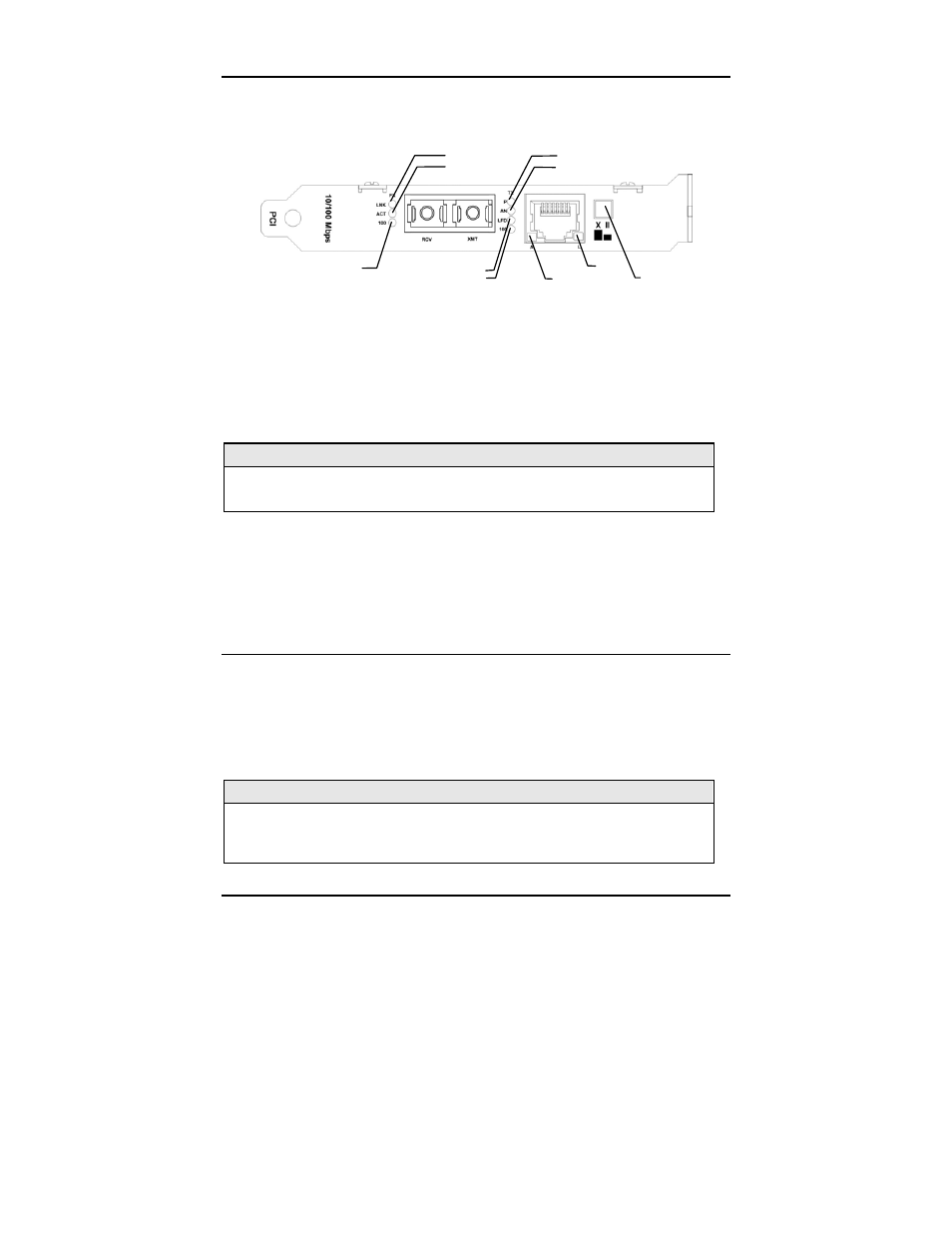
LED Indicators (PCI Version)
The McPC 10/100 features four diagnostic LEDs. The following are the LED
functions on the twisted pair port:
FX Link LED Power LED
FX Activity LED Auto Negotiation LED
FX 100 Mbps Active LED
Link Fault Detection LED TX Link
TX 100 Mbps Activity LED TX Activity Crossover/ Pass-
Through Switch
Twisted Pair Port
P
Green when the unit has power
AN
Green when Auto Negotiation mode is enabled
LFD
Green when Link Fault Detection is enabled
100
Yellow when a 100 Mbps connection is detected
NOTE
This feature is only available when either Force 10 or Force 100 mode is
enabled. For more on this feature, see the LFD LED Activity section, below.)
Fiber Port
LNK
Green when a twisted pair link is established
ACT
Yellow when activity is detected on the port
100
Yellow when a 100 Mbps connection is detected
Link Fault Detection LED Activity (PCI Version)
When LFD is enabled and a fault occurs on a segment of the media conversion,
the various Link LEDs in that conversion will either blink or extinguish. LEDs may
react differently depending on the type of end devices in the conversion, whether
the McPC 10/100 is in Force 10 or Force 100 mode, where the fault occurs, etc.
For questions, please contact Technical Support.
NOTE
Twisted pair AND fiber optic cables must be connected, and the twisted pair
crossover/pass-through switch set correctly, before either LNK LED will glow
solid.