Produ ct i nfo rmati o n b&b e lectr on ics – B&B Electronics FOSTC - Datasheet User Manual
Page 4
FOSTC-0812-4/6
© 2002 by B&B Electronics. All rights reserved.
www.bb-elec.com [email protected] [email protected]
International Office: 707 Dayton Road PO Box 1040 Ottawa, IL 61350 USA 815-433-5100 Fax 433-5104
European Office: Westlink Commercial Park Oranmore Co. Galway Ireland +353 91 792444 Fax +353 91 792445
PRODU
CT I
NFO
RMATI
O
N
B&B E
LECTR
ON
ICS
Multi-Drop Operation
A multi-drop configuration is created by forming a ring of FOSTCs (see Figure 1). Whichever serial device sends data,
all other devices receive it. The data is repeated around the fiber ring until it reaches the source, where it is blocked.
There is no echo back to the serial side of the sending device. Each fiber transmitter must be connected to the
following converter’s receiver. Set SW1:6 to the “On” position on all FOSTCs in the ring. Any device can be full-duplex
(RS-232, RS-422, or four-wire RS-485), or half duplex RS-485. Because all data shares the same path on the ring,
only one device can send data at a time.
Interfacing to Fiber Devices from Other Manufacturers
Note: The factory default for the LED emitter is to have the light ON in the idle state. To interconnect with other devices
that have the light OFF in the idle state, this unit would need to be modified. To modify the unit so that the light is OFF
in the idle state, contact B&B Electronics Technical Support.
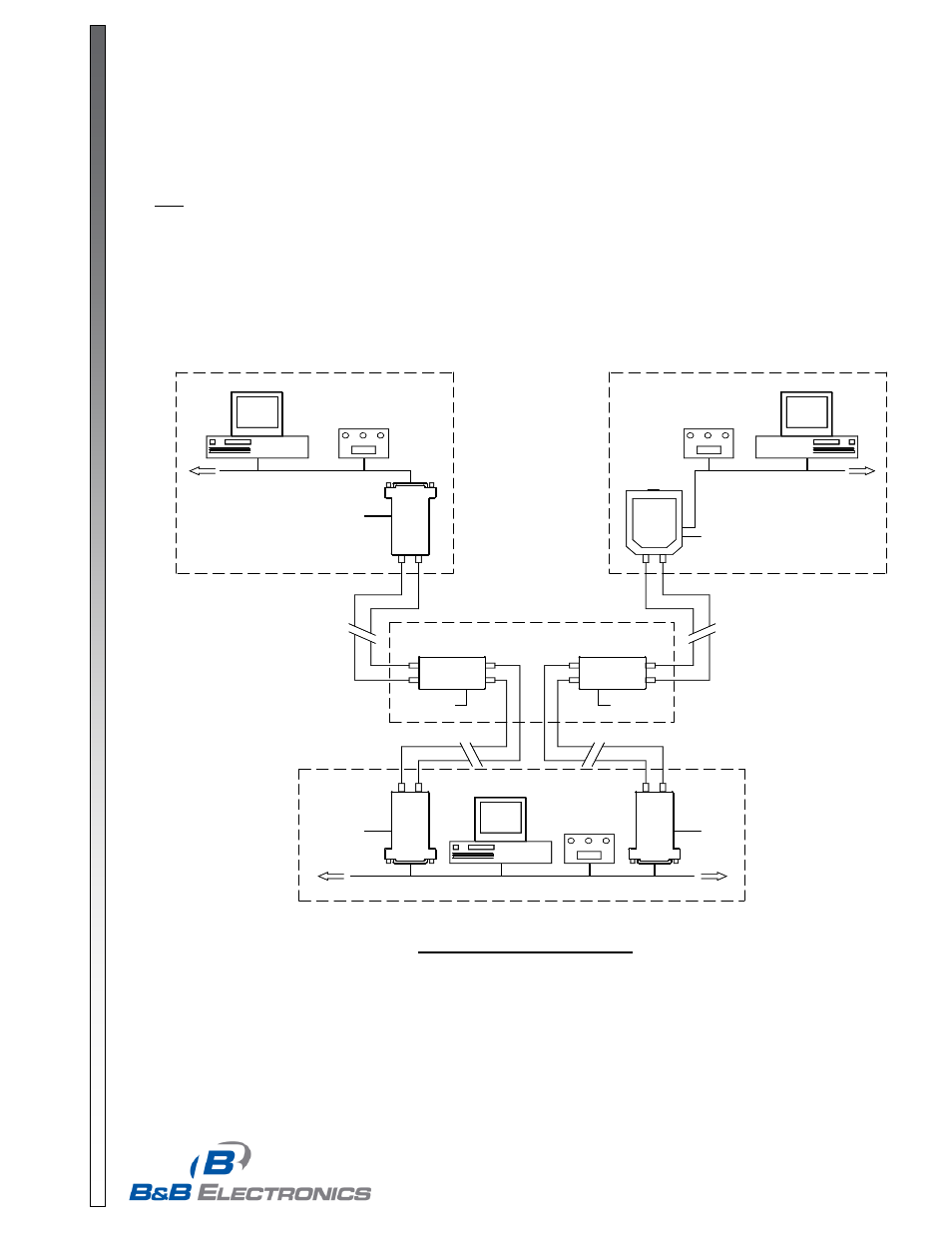
Typical Installation Configuration
Below is a University Campus setup that illustrates the basic configuration of a typical Fiber Optic Network. This
scenario uses a combination of B&B Fiber devices including 3 of the FOSTCs, 2 of the fiber repeaters FOSTDRP, and
one of the DIN Rail mount Fiber Converters FOSTCDR. Each of the items requires a power supply (not shown).
RS-485 NETWORK
F
OST
C
FOSTDRP
RX
TX
TX
RX
TX
RX
RS-485 NETWORK
F
OST
CD
R
RS-485 NETWORK
F
OST
C
TX
RX
F
OST
C
TX
RX
FOSTDRP
RX
TX
TX
RX
BUILDING A
BUILDING B
BUILDING C
UP TO 2.5 MILES
UP TO 2.5 MILES
UP TO 2.5 MILES
UP TO 2.5 MILES
CENTRAL PATCH BUILDING
+12 VDC
+10 to 30 VDC
+12 VDC
+12 VDC
+10 to 30 VDC
RX
TX
+10 to 30 VDC
Figure 4. Typical Campus Setup