Produ ct i nfo rmati o n b&b e lectr on ics, Rs-232 connections – B&B Electronics FOSTC - Datasheet User Manual
Page 2
FOSTC-0812-2/6
© 2002 by B&B Electronics. All rights reserved.
www.bb-elec.com [email protected] [email protected]
International Office: 707 Dayton Road PO Box 1040 Ottawa, IL 61350 USA 815-433-5100 Fax 433-5104
European Office: Westlink Commercial Park Oranmore Co. Galway Ireland +353 91 792444 Fax +353 91 792445
PRODU
CT I
NFO
RMATI
O
N
B&B E
LECTR
ON
ICS
to-connector power budget is 12.1 dB. Because 62.5/125 m cable typically has a line attenuation of 3 dB per Km at
820 nm, the 12.1 dB power budget translates into 2.5 miles. This assumes no extra connectors or splices in the link.
Each extra connection would typically add 0.5 dB of loss, reducing the possible distance by 166 m (547 ft.). The actual
loss should be measured before assuming distances.
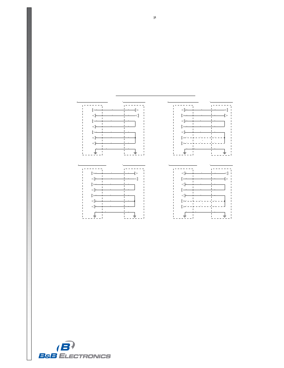
RS-232 Connections
Connection of the FOSTC is simple and straightforward. The DB25 female serial connector is used for connecting to
either RS-232, RS-422 or RS-485. The RS-232 signals are pinned as a DCE device (input on Pin 2 and output on Pin
3). A straight through cable can be used from your DB25 port on any DTE device such as a PC or terminal. A standard
9 to 25-pin adapter can be used in cases where the serial port on the DTE device is a DB9. A null modem cable or
adapter that swaps pins 2 and 3 is needed for connecting to modems or other DCE devices. See Figure 2 for
connection diagrams to 9 pin and 25 pin DTE and DCE devices. Because RS-422 and RS-485 signals are also
available on the same connector, take special care not to hook any external signals to these pins. This is not a problem
for most serial devices, but a custom cable must be made that does not connect to the extra pins on the DB25
connector if your device has power or special non-standard outputs.
RS-422 & RS-485 Connections
The RS-422/485 driver and receiver are connected to 4 pins on the DB25 connector. Signal ground is on Pin 7. When
connecting to a four-wire RS-422/485 device or system, connect the output of your device to pins 16 (B or +) and 17 (A
or +). Connect the input to your device to pins 14 (B or +) and 15 (A or -). For two-wire RS-485 systems, the driver and
receiver of the FOSTC must be connected together by tying pins 14 and 16 together and 15 and 17 together. This
allows the FOSTC to communicate half-duplex over the same pair. Refer to Figure 3 for connection diagrams to your
RS-422 or RS-485 equipment.
If termination is needed, a spot on the PCBD of the FOSTC labeled Rt allows you to solder in a termination resistor
across the RD(A) and RD(B) lines. Removing R8 and R16 and replacing them with through-hole components can also
change the off-state bias resistor values. Before making modifications to the FOSTC, be sure to consult B&B
Electronics’ free RS-422/485 Application Note or other sources of information to see if termination is necessary. The
Application Note is available from our Web site, or call and we will be happy to send you one at no charge.
Figure 2: RS-232 Connection Diagrams
DB9 DTE Device
TD
RD
RTS
CTS
DTR
DSR
DCD
Signal GND
3
2
7
8
4
6
1
5
DB9 DCE Device
TD
RD
RTS
CTS
DTR
DSR
DCD
Signal GND
3
2
7
8
4
6
1
5
DB25 DTE Device
FOSTC DB25
TD
RD
RTS
CTS
DTR
DSR
DCD
Signal GND
2
3
4
5
20
6
8
7
2
3
4
5
20
6
8
7
or
DB25 DCE Device
TD
RD
RTS
CTS
DTR
DSR
DCD
Signal GND
3 (RD)
2 (TD)
4
5
20
6
8
7
or
FOSTC DB25
FOSTC DB25
FOSTC DB25
2
3
4
5
6
8
7
2
3
4
5
20
6
8
7
3 (RD)
2 (TD)
4
5
20
6
8
7