Produ ct i nfo rmati o n b&b e lectr on ics – B&B Electronics FOSTC - Datasheet User Manual
Page 3
FOSTC-0812-3/6
© 2002 by B&B Electronics. All rights reserved.
www.bb-elec.com [email protected] [email protected]
International Office: 707 Dayton Road PO Box 1040 Ottawa, IL 61350 USA 815-433-5100 Fax 433-5104
European Office: Westlink Commercial Park Oranmore Co. Galway Ireland +353 91 792444 Fax +353 91 792445
PRODU
CT I
NFO
RMATI
O
N
B&B E
LECTR
ON
ICS
Table 1: RS-485 Timeout Selection
Baud Rate Pos. 1 Pos. 2 Pos. 3 Pos. 4 Pos. 5
R9
Time(ms)
1200
ON
OFF
OFF
OFF
OFF
820 K
8.20
2400
ON
OFF
OFF
OFF
OFF
430 K
4.30
4800
OFF
OFF
OFF
OFF
ON
Not Used
2.20
9600
OFF
OFF
OFF
ON
OFF
Not Used
1.30
19.2K
OFF
OFF
ON
OFF
OFF
Not Used
0.56
38.4K
OFF
ON
OFF
OFF
OFF
Not Used
0.27
57.6K
ON
OFF
OFF
OFF
OFF
Not Used
0.22
76.8K
ON
OFF
ON
ON
OFF
Not Used
0.14
115.2K
ON
ON
ON
OFF
OFF
Not Used
0.10
153.6K
ON
OFF
OFF
OFF
OFF
6.2 K
0.06
230.4K
ON
OFF
OFF
OFF
OFF
4.3 K
0.04
460.8K
ON
OFF
OFF
OFF
OFF
2.2 K
0.02
Table 2: 422/485 Switch Settings
Position 7
TX Enable
Position 8
RX Enable
RS-485
2-Wire Mode
(half duplex)
ON
ON
RS-485
4-Wire Mode
(full duplex)
ON
OFF
RS-422 Mode
(full duplex)
OFF
OFF
Dip-Switch Setup
The Dip-Switch (SW1) on the FOSTC
defines the mode of operation when being used
for RS-422 or RS-485. Positions 1 through 5 on
the switch determine the timeout of the RS-485
driver. Because the driver is controlled by
hardware, a specific time must be set to tell the
hardware how long to wait for data on the fiber
side before turning off the RS-422/485 driver. If
this time is set too short, the driver could be
disabled before transmission is complete,
resulting in data corruption. If the time is set too
long, the RS-485 device may respond before
the RS-422/485 driver in the FOSTC is
disabled, corrupting this response. We
recommend that the timeout be set for
approximately one character time or longer.
The character times for several different baud
rates are selectable on switch positions 1
through 5. If you need a different timeout than what is provided, R10 can be removed and replaced with a different
value R9. Table 1 shows different timeout values for the switch positions as well as typical R9 replacement values.
Position 6 of SW1 sets the unit in a “Multidrop” mode or a “Point-to-Point” mode. When the FOSTC is set in a
“Multidrop” mode, data arriving on the Fiber Optic receiver is repeated back out the transmitter. When set in a “Point-
to-
Point” mode, data arriving at the Fiber optic receiver is not sent back out the Fiber Optic transmitter. Position 6 must
be turned “On” when the FOSTC is to be used in a multi-drop ring configuration. It must be turned “Off” when the
FOSTC is to be used as either end of a point-to-point communication line. See Figure 3 for typical system setups using
the FOSTC in its different modes.
Positions 7 and 8 of SW1 determine when the RS-422/485 driver
and receiver are enabled. Position 7 controls the driver and Position
8 controls the receiver. For RS-422 operation, set both switches to
t
he “Off” position. For multi-drop RS-485 four-wire systems, position
7 should be “On” and position 8 should be “Off.” This allows the
receiver to be enabled all of the time and eliminates some possible
timing problems. For RS-485 two-wire systems, both switches
should be in the “On” position. This disables the RS-422/485
receiver whenever the driver is enabled, preventing data from being
echoed back to the fiber side of the FOSTC.
Table 2 illustrates the switch settings for typical setups.
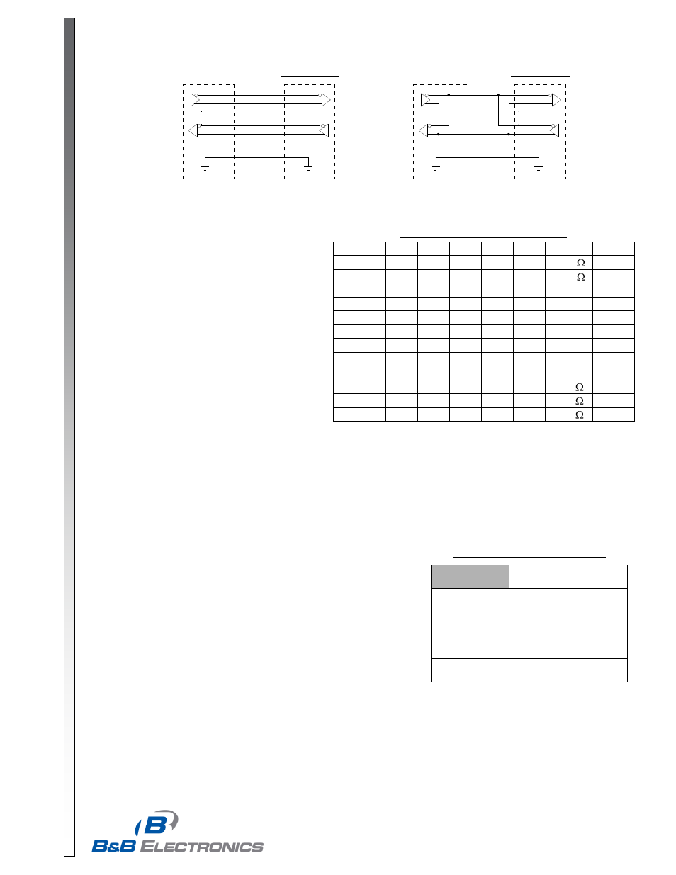
Figure 3: RS-422/485 Connection Diagrams
422/485 4W Device
TD A (-)
TD B (+)
16 RD B
17 RD A
14 TD B
15 TD A
RD A (-)
RD B (+)
7
GND
FOSTC DB25
485 2 Wire Device
Data A (-)
16 RD B
17 RD A
14 TD B
15 TD A
Data B (+)
7
GND
FOSTC DB25