B&B Electronics FOSTC - Datasheet User Manual
Produ ct i nfo rmati o n b&b e lectr on ics, Model fostc, Description
FOSTC-0812-1/6
© 2002 by B&B Electronics. All rights reserved.
www.bb-elec.com [email protected] [email protected]
International Office: 707 Dayton Road PO Box 1040 Ottawa, IL 61350 USA 815-433-5100 Fax 433-5104
European Office: Westlink Commercial Park Oranmore Co. Galway Ireland +353 91 792444 Fax +353 91 792445
PRODU
CT I
NFO
RMATI
O
N
B&B E
LECTR
ON
ICS
TX
RX
FOSTC
RX
TX
FOSTC
RS-232
RS-422
or RS-485
Device
Duplex
Multimode
Fiber
or System
RS-232
RS-422
or RS-485
Device
or System
SW1:6 = OFF
SW1:6 = OFF
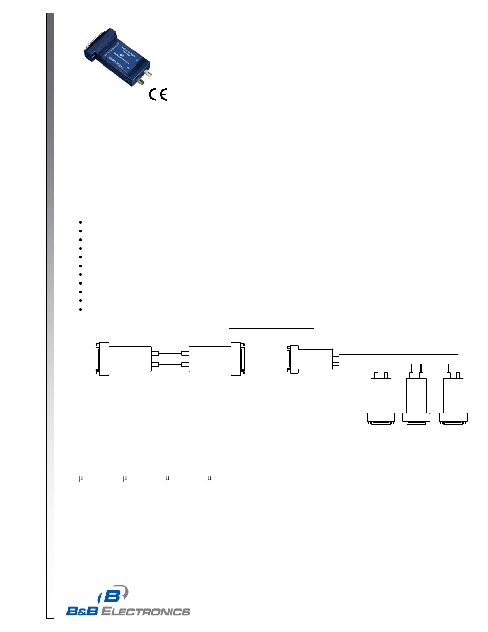
Point to Point
TX
RX
FOSTC
RX
TX
FO
S
TC
RS-232
RS-422
or RS-485
Device
Multimode
Fiber
or System
RS-232
RS-422
or RS-485
Device
or System
RX
TX
FO
S
TC
RS-232
RS-422
or RS-485
Device
or System
RX
TX
FO
S
TC
RS-232
RS-422
or RS-485
Device
or System
SW1:6 = ON
SW
1:
6
=
ON
SW
1:
6
=
ON
SW
1:
6
=
ON
Multi-Drop Ring
Model FOSTC
RS-232, 422 or 485 Signals Up To
2.5 Miles with Fiber Optic Modem
Description
Fiber optic cabling has inherent resistance to EMI/RFI and transient immunity, making it ideal for industrial and utility
data communication applications.
The FOSTC was designed to provide the most versatile connection possible between any asynchronous serial
equipment using Fiber Optic cable. The FOSTC can be used for point-to-point communications between serial devices,
or in a multi-drop fiber ring configuration, allowing multiple serial devices to communicate with each other.
It allows any two pieces of asynchronous serial equipment to communicate full or half-duplex over two fibers at typical
distances up to 2.5 miles (4 km). To extend the distance of the fiber link beyond 2.5 miles, use B&B model FOSTDRP
Fiber Optic Repeater.
Features/Applications
Point-to-point or multi-drop ring configuration
RS-232, RS-422, or RS-485 operation
Use as a converter from RS-232 to RS-422/485
RS-422/485 data rates up to 500 kbps
RS-485 Automatic Send Data driver control
Inherent EMI/RFI and transient immunity.
Eliminate ground loops
Extend serial signals up to 2.5 miles
Uses popular ST type fiber connectors
Standard DB25 female (DCE) for serial connections
12VDC powered (separate supply required)
Figure 1: Typical Setups
Fiber Optic Connections
The FOSTC uses a separate LED emitter and photo-detector operating at 820 nm wavelength. Connections to the
emitter and detector are on ST type connectors. Almost any multimode glass fiber size can be used including 50/125
m, 62.5/125 m, 100/140 m, and 200 m. One fiber is required for each connection between a transmitter and
receiver. In a point-to-point configuration, two fibers are required between the two modems, one for data in each
direction. A multi-drop ring configuration requires one fiber between TX and RX around the loop. See Figure 1 for
typical point-to-point and multi-drop configurations.
The most important consideration in planning the fiber o
ptic link is the “power budget” of the fiber modem. This value
represents the amount of loss in dB that can be present in the link between the two modems before the units fail to
perform properly. This value includes line attenuation as well as connector loss. For the FOSTC the typical connector-