Rs-485 2-wire – B&B Electronics FOSTCDRI-ST - Quick Start Guide User Manual
Page 2
p/n 8405 FOSTCDRI-Sx-1112qsg-2/4
© 2009 by B&B Electronics. All rights reserved.
www.bb-elec.com [email protected] [email protected]
International Office: 707 Dayton Road PO Box 1040 Ottawa, IL 61350 USA 815-433-5100 Fax 433-5104
European Office: Westlink Commercial Park Oranmore Co. Galway Ireland +353 91 792444 Fax +353 91 792445
PR
O
D
U
C
T
INF
ORM
A
TIO
N
B
&
B
ELE
C
T
R
ON
ICS
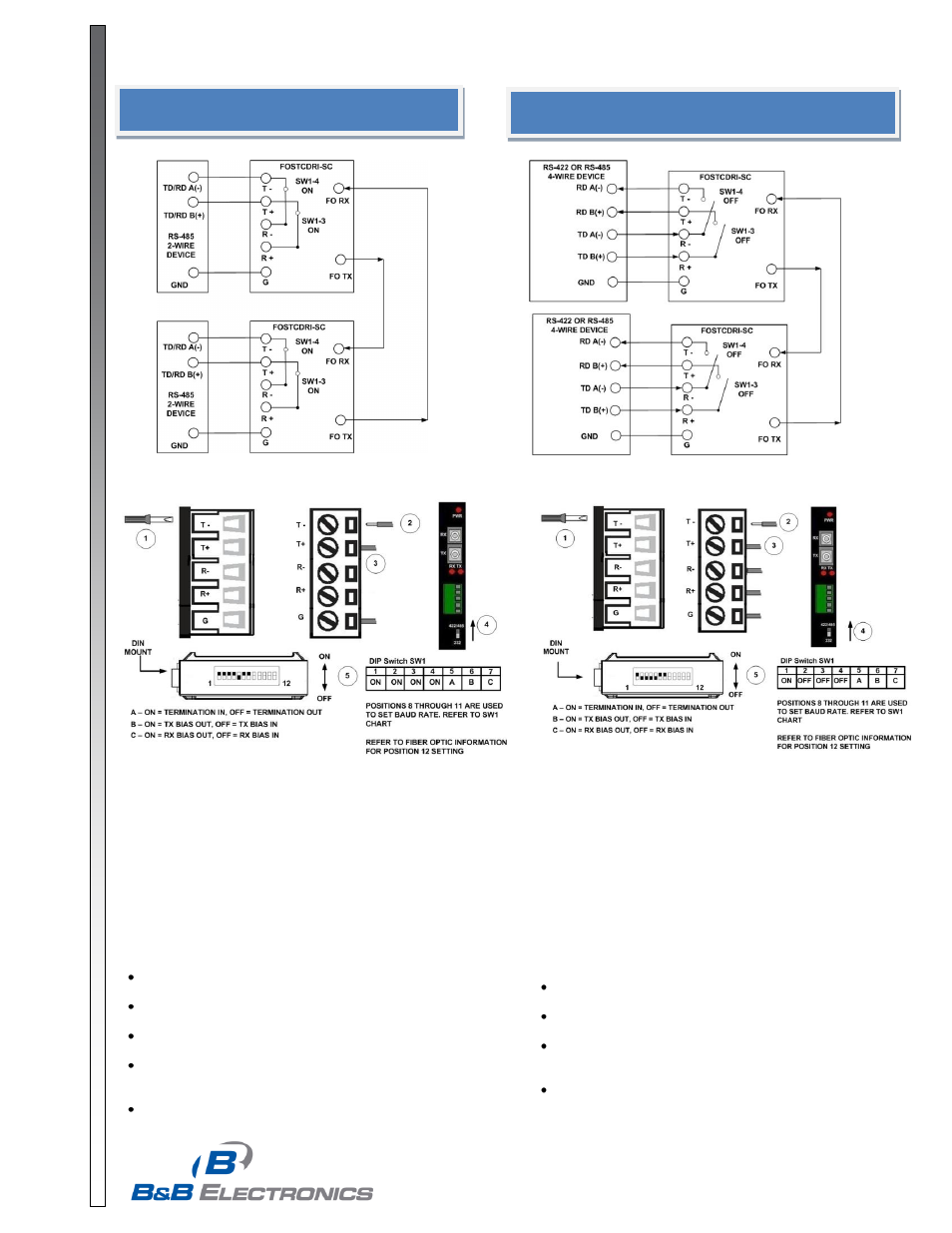
RS-485 2-Wire
1. Loosen the screws to open the Serial TB Lead Clamps for the T-,
T+, and G terminals.
2. Insert the RS-485 2-Wire Signals Leads. The TB will accept 12 to
28 AWG wire.
3. Tighten the screws to close the Serial TB Lead Clamps. Ensure
the clamps hold the leads securely. However, do not over tighten.
4. Position the 422/485/232 Switch to the 422/485 position.
5. Configure the DIP Switch on the bottom of the converter for RS-
485 2-Wire operation.
Installation Notes:
In 2-Wire mode, T(-) and T(+) terminals are tied to the R(-) and
R(+) terminals with DIP Switch SW1-3 and SW1-4.
If Termination is required, a 1
20Ω resister can be placed
across the R(-) and R(+) terminals by setting SW1-5 to ON.
This converter has 1.2
KΩ pull-up/down bias resistors built
in. To use this bias, set SW1-6 and SW1-7 to ON.
B&B Electronics’ RS-485 Application Note contains more
information about termination and biasing. This reference is
available on our web site.
For a replacement TB, order part number 7466.
RS-422 / RS-485 4-Wire
1. Loosen the screws to open the Serial TB Lead Clamps for the
T-, T+, R-, R+, and G terminals.
2. Insert the RS-422/485 4-Wire Signal Leads. The TB will
accept 12 to 28 AWG wire.
3. Tighten the screws to close the Serial TB Lead Clamps.
Ensure the clamps hold the leads securely. However, do not
over tighten.
4. Position the 422/485/232 Switch to the 422/485 position.
5. Configure the DIP Switch on the bottom of the converter for
RS-422/485 4-Wire operation.
Installation Notes:
If Termination is required, a 120Ω resister can be placed
across the R(-) and R(+) terminals by setting SW1-5 to ON.
This converter has 1.2
KΩ pull-up/down bias resistors
built in. To use this bias, set SW1-6 and SW1-7 to ON.
B&B Electronics’ RS-485 Application Note contains more
information about termination and biasing. This reference
is available on our web site.
For a replacement TB, order part number 7466.