Thermocouple circuit with software compensation – Rainbow Electronics MAX111 User Manual
Page 21
unloaded, and subtracting this value from actual weight
measurements. The lowpass filtering action of the
MAX111’s sigma-delta converter helps minimize noise.
The resolution of the weigh scale can be further
increased by averaging several conversions.
Thermocouple Circuit with Software
Compensation
A thermocouple is created by the junction of dissimilar
metals, and generates a voltage proportional to temper-
ature (Seebeck voltage), making it useful for tempera-
ture-measurement instruments. When a thermocouple
probe is connected to a measurement instrument, other
thermoelectric potentials are created between the alloys
of the probe and the copper connectors of the instru-
ment. These potentials introduce a temperature-depen-
dent error that must be subtracted from the temperature
measurement to obtain an accurate result. According to
the law of intermediate metals, the junction of the ther-
mocouple-probe alloys with the copper of the instrument
junction block can be treated as another thermocouple
of the same type. The voltage measured by the instru-
ment can be expressed as:
V =
α
(T1 - T
REF
)
where
α
is the Seebeck constant for the type of thermo-
couple, T1 is the temperature being measured, and
T
REF
is the temperature of the junction block. Although
one method to obtain T
REF
is to force the junction block
to a known temperature (0°C), a more popular
approach is to measure T
REF
directly using a thermistor
or PN junction voltage.
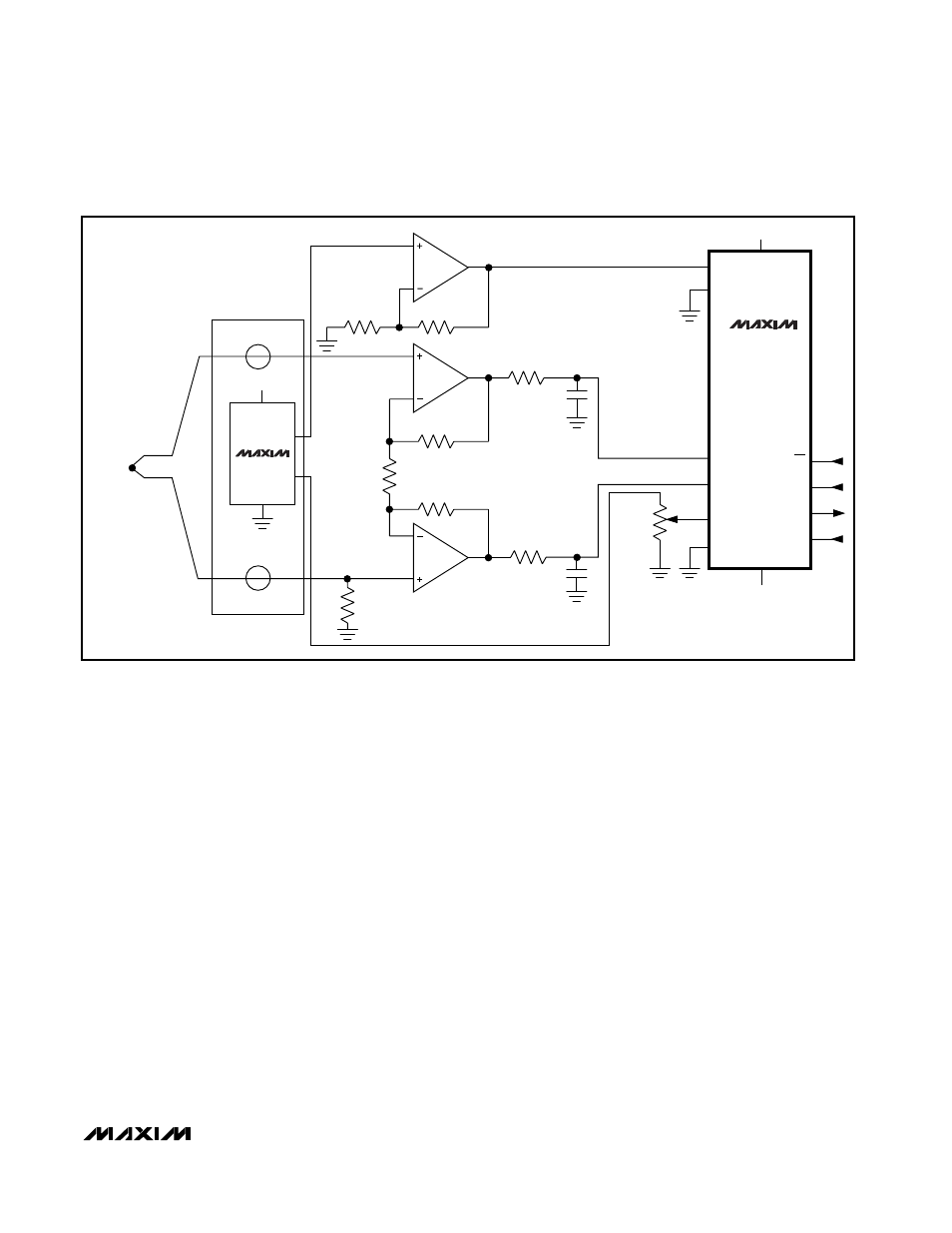
The circuit in Figure 12 shows a k-type thermocouple
going through a 54dB gain stage to channel 1 of the
MAX110. A MAX874 voltage reference provides both
the 3V reference voltage and reference junction tem-
perature information to the MAX110. Armed with the
temperature information provided by the MAX874, the
thermocouple voltage created at the junction block can
be subtracted out in software. The TEMP output of the
MAX874 is nominally 690mV at room temperature, and
increases with temperature at about 2.3mV/°C. Place
the MAX874 as close as possible to the terminal block,
and ensure good thermal contact between them. This
circuit employs a common k-type thermocouple and,
with the component values shown, can indicate tem-
peratures in the range of -150°C to +125°C.
MAX110/MAX111
Low-Cost, 2-Channel, ±14-Bit Serial ADCs
______________________________________________________________________________________
21
243k
1k
1k
10k
1µF
1µF
IN1+
IN1-
REF-
REF+
V
SS
-5V
CS
DIN
DOUT
SCLK
243k
1M
1k
10k
10k
K-TYPE
V
DD
+5V
IN2-
IN2+
MAX110
1/4 MAX479
1/4 MAX479
1/4 MAX479
TEMP
OUT
V
IN
MAX874
+5V
Figure 12. Thermocouple Circuit with Software Compensation