Oversampling clock – Rainbow Electronics MAX111 User Manual
Page 10
MAX110/MAX111
Low-Cost, 2-Channel, ±14-Bit Serial ADCs
10
______________________________________________________________________________________
Oversampling Clock
XCLK internally connects to a clock-frequency divider
network, whose output is the ADC oversampling clock,
f
OSC
. This allows the selected clock source (internal RC
oscillator or external clock applied to XCLK) to be
divided by one, two, or four (see
Clock Divider-Ratio
Control Bits
).
Figure 3 shows the two methods for providing the over-
sampling clock to the MAX110/MAX111. In external-
clock mode (Figure 3a), the internal RC oscillator is
disabled and XCLK accepts a TTL/CMOS-level clock to
provide the oversampling clock to the ADC.
Select external-clock mode (Figure 3a) by connecting
RCSEL to GND and a TTL/CMOS-compatible clock to
XCLK (see
Selecting the Oversampling Clock
Frequency
).
In RC-oscillator mode (Figure 3b), the internal RC oscil-
lator is active and its output is connected to XCLK
(Figure 1). Select RC-oscillator mode by connecting
RCSEL to V
DD
. This enables the internal oscillator and
connects it to XCLK for use by the ADC and external
system components. Minimize the capacitive loading on
XCLK when using the internal RC oscillator.
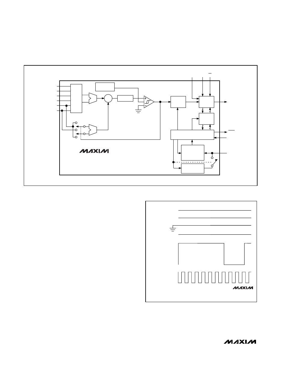
DIFFERENTIAL
ANALOG
INPUT
V
REF+
DC LEVEL AT 1/2 V
REF
V
REF-
V
REF+
V
REF-
OUTPUT FROM
1-BIT DAC
OVERSAMPLING
CLOCK
MAX110
MAX111
Figure 2. ADC Waveforms During a Conversion
Figure 1. Functional Diagram
IN1+
IN+
IN-
INPUT
MUX
IN1-
IN2+
IN2-
REF+
Gm
REF-
Gm
INTEGRATOR
UP/DOWN
COUNTER
-
Σ
∫
DITHER
GENERATOR
SERIAL
SHIFT
REGISTER
DIN
SCLK CS
16
16
16
16
CONTROL
REGISTER
DOUT
BUSY
RCSEL
XCLK
OSC
TIMER + CONTROL
LOGIC + CLOCK GENERATOR
DIVIDER
NETWORK,
DIVIDE BY
1, 2, OR 4
RC
OSCILLATOR
MAX110
MAX111