Table 3. procedure to calibrate the adc – Rainbow Electronics MAX111 User Manual
Page 16
MAX110/MAX111
Low-Cost, 2-Channel, ±14-Bit Serial ADCs
16
______________________________________________________________________________________
X = Don't Care
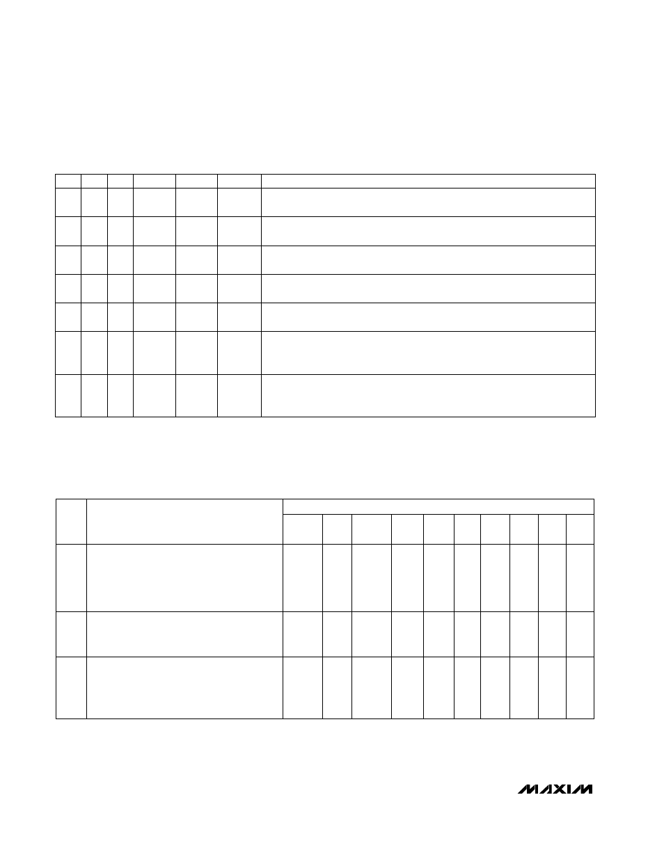
Table 3. Procedure to Calibrate the ADC
0
0
1
0
0
or
1
00
XX
No
Change
00
1
Performs an offset-null conversion with the
internal ADC inputs shorted to the selected
input channel's negative input (IN1- or IN2-).
The next operation performs the first signal
conversion with the new setup.
3
0
0
0
1
X
00
XX
No
Change
00
1
Performs a gain-calibration conversion with
the null register contents as the starting value.
The result is stored in the calibration register.
2
0
0
1
1
X
00
XX
New
Data
00
1
Sets the new conversion speed (if required)
and performs an offset correction conversion
with the internal ADC inputs shorted to REF-.
The result is stored in the null register.
(This step also selects the speed/resolution
for the ADC.)
1
PD
PDX
NUL
CAL
CHS
Not
Used
DV2 &
DV4
CONV1-
CONV4
Not
Used
N
NO
O--O
OP
P
DESCRIPTION
STEP
CONTROL WORD
X = Don't Care
Table 2. Allowable Input Multiplexer Configurations
Input control word is not transferred to the control register. ADC
configuration remains unchanged and no new conversion starts when CS
returns high.
No
Change
No
Change
0
X
X
X
REF+ and REF- connected to the ADC inputs; gain-calibration mode
selected. Autocal conversion begins when CS returns high, and the results are
stored in the 16-bit I/O register.
REF-
REF+
1
X
0
1
REF- connected to the ADC inputs; offset-null mode selected. Autonull conversion
begins when CS returns high, and the results are stored in the null register.
REF-
REF-
1
X
1
1
IN2- connected to the ADC inputs; offset-null mode selected. Autonull conversion
begins when CS returns high, and the results are stored in the null register.
IN2-
IN2-
1
1
1
0
IN1- connected to the ADC inputs; offset-null mode selected. Autonull conversion
begins when CS returns high, and the results are stored in the null register.
IN1-
IN1-
1
0
1
0
Channel 2 connected to ADC inputs. Conversion begins when CS returns high.
IN2-
IN2+
1
1
0
0
Channel 1 connected to ADC inputs. Conversion begins when CS returns high.
IN1-
IN1+
1
0
0
0
DESCRIPTION
ADC IN-
ADC IN+
N
NO
O--O
OP
P
CHS
NUL
CAL