Applications information, Layout, grounding, bypassing – Rainbow Electronics MAX111 User Manual
Page 19
MAX110/MAX111
Low-Cost, 2-Channel, ±14-Bit Serial ADCs
______________________________________________________________________________________
19
A 100ms conversion time cannot be achieved with either
10,240 CCPC or 20,480 CCPC modes because f
OSC
would be below the minimum 250kHz requirement.
When the gain calibration is performed, the conversion
times change approximately 1% to compensate for the
modulator’s gain error. This slightly degrades the line-
frequency rejection, because the corrected conversion
time is no longer an exact multiple of the line frequency.
Typically, the rejection of 50Hz/60Hz from the converter
is 55dB; i.e., if there is 100mV injection at the reference
or the analog input pin, it will cause an uncertainty of
±0.006%. If the system has large 50Hz/60Hz noise, the
use of internal auto gain calibration is not recommend-
ed. Instead, gain calibration should be done off-chip,
using numerical computation methods.
If you wish to use a configuration other than those sug-
gested in Table 6, you can accomplish similar 50Hz
and 60Hz line-frequency rejection off-chip by averag-
ing several conversions.
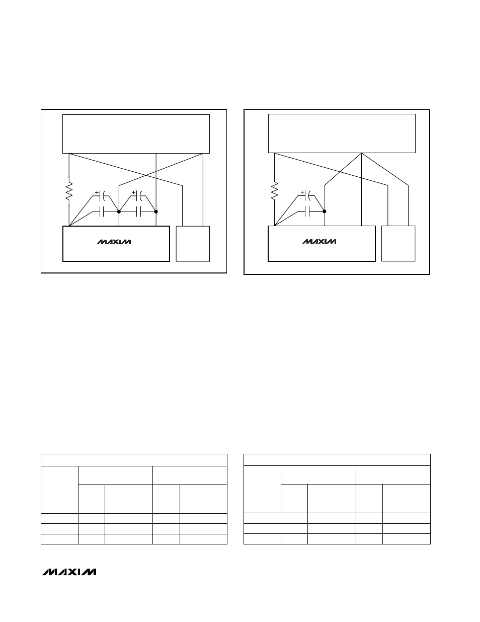
__________Applications Information
Layout, Grounding, Bypassing
For minimal noise, bypass each supply to GND with a
0.1µF capacitor. A ground plane should also be placed
under the analog circuitry. To minimize the coupling
effects of stray capacitance, keep digital lines as far
from analog components and lines as possible. Figure
10 shows the suggested power-supply and ground-
plane connections.
*R = 10
Ω
*OPTIONAL
DIGITAL
CIRCUITRY
POWER
SUPPLIES
V
DD
V
SS
+5V
DGND
+5V
-5V
GND
GND
4.7
µ
F
0.1
µ
F
0.1
µ
F
4.7
µ
F
MAX110
Figure 10a. MAX110 Power-Supply Grounding Connections
*R = 10
Ω
*OPTIONAL
DIGITAL
CIRCUITRY
POWER
SUPPLIES
V
DD
AGND
+5V
DGND
+5V
GND
GND
4.7
µ
F
0.1
µ
F
MAX111
Figure 10b. MAX111 Power-Supply Grounding Connections
CCPC = Clock Cycles per Conversion
Table 6. Suggested XCLK Frequencies to Achieve Maximum Rejection of Both 50Hz/60Hz Line
Frequencies
MAX111 (t
CONVERT
= 200ms)
81,240 CCPC
102,400 CCPC
DIVIDER
RATIO
f
XCLK
(MHz)
RELATIVE
ACCURACY
(%)
f
XCLK
(MHz)
RELATIVE
ACCURACY
(%)
1:1
0.4062
0.030
0.512
0.030
2:1
0.8124
0.025
1.024
0.025
4:1
1.6248
0.022
2.048
0.023
MAX110 (t
CONVERT
= 100ms)
81,240 CCPC
102,400 CCPC
DIVIDER
RATIO
f
XCLK
(MHz)
RELATIVE
ACCURACY
(%)
f
XCLK
(MHz)
RELATIVE
ACCURACY
(%)
1:1
0.8124
0.025
1.024
0.065
2:1
1.6248
0.018
2.048
0.045
4:1
3.2496
0.016
4.096
0.030