Max104, Static parameter definitions, Integral nonlinearity (inl) – Rainbow Electronics MAX104 User Manual
Page 26: Differential nonlinearity (dnl)
MAX104
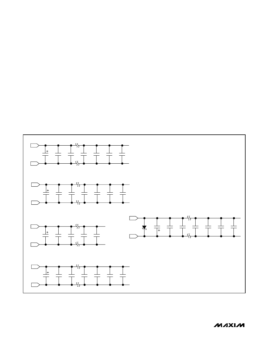
All supplies should be decoupled with large tantalum or
electrolytic capacitors at the point where they enter the
PCB. For best performance, bypass all power supplies
to the appropriate ground with a 10µF tantalum capaci-
tor, to filter power-supply noise, in parallel with a 0.01µF
capacitor and a high-quality 47pF ceramic chip capaci-
tor located very close to the MAX104 device, to filter
very high-frequency noise.
Static Parameter Definitions
Integral Nonlinearity (INL)
Integral nonlinearity is the deviation of the values on an
actual transfer function from a straight line. This straight
line can be either a best-straight-line fit or a line drawn
between the endpoints of the transfer function, once
offset and gain errors have been nullified. The static lin-
earity parameters for the MAX104 are measured using
the best-straight-line fit method.
Differential Nonlinearity (DNL)
Differential nonlinearity is the difference between an
actual step width and the ideal value of 1LSB. A DNL
error specification of less than 1LSB guarantees no
missing codes and a monotonic transfer function.
±5V, 1Gsps, 8-Bit ADC with
On-Chip 2.2GHz Track/Hold Amplifier
26
______________________________________________________________________________________
10
µ
F
GNDD
V
CC
D
GNDA
V
CC
A
GNDI
V
CC
I
GNDI
1N5817
V
EE
V
CC
A = +4.75V TO +5.25V
V
CC
D = +4.75V TO +5.25V
V
CC
I = +4.75V TO +5.25V
V
CC
O = +3.0V TO V
CC
D
V
EE
= -4.75V TO -5.25V
NOTE:
LOCATE ALL 47pF CAPACITORS AS CLOSE
AS POSSIBLE TO THE MAX104 DEVICE.
GNDD
V
CC
O
10nF
10nF
47pF
47pF
47pF
47pF
10
µ
F
10nF
10nF
47pF
47pF
47pF
47pF
10
µ
F
10nF
10nF
47pF
47pF
10
µ
F
10nF
10nF
47pF
47pF
47pF
47pF
10
µ
F
10nF
10nF
47pF
47pF
47pF
47pF
Figure 22. MAX104 Bypassing and Grounding