Max104, Applications information, Table 2. demultiplexer operation – Rainbow Electronics MAX104 User Manual
Page 16
MAX104
Decimation DIV4 Mode
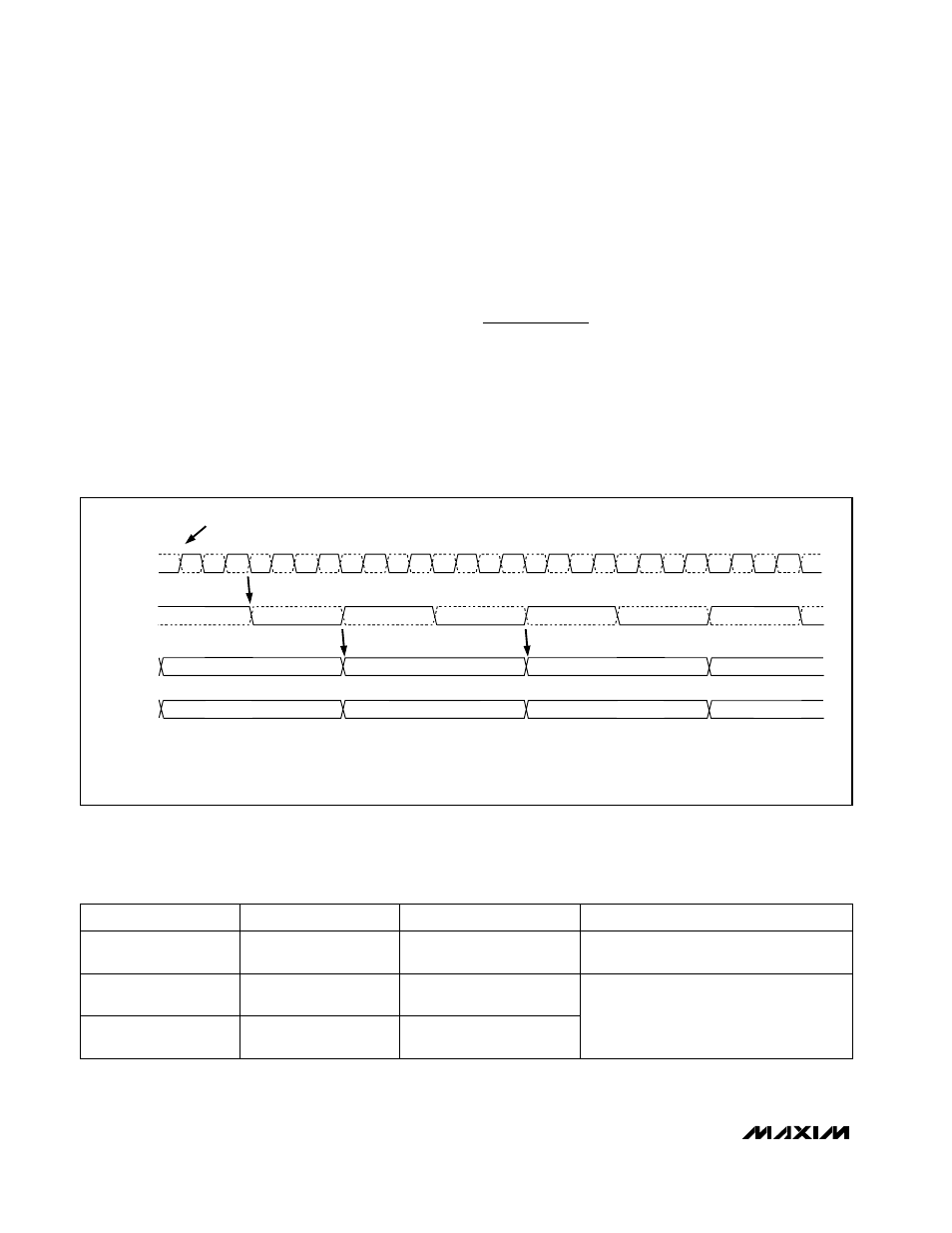
The MAX104 also offers a special decimated, demulti-
plexed output (Figure 8) that discards every other input
sample and outputs data at one-quarter the input sam-
pling rate for system debugging at slower output data
rates. With an input clock of 1GHz, the effective output
data rate will be reduced to 250MHz per output port in
the DIV4 mode (Table 2). Since every other sample is
discarded, the effective sampling rate is 500Msps.
Overrange Operation
A single differential PECL overrange output bit (OR+,
OR-) is provided for both primary and auxiliary demulti-
plexed outputs. The operation of the overrange bit
depends on the status of the internal demultiplexer. In
demultiplexed DIV2 mode and decimation DIV4 mode,
the OR bit will flag an overrange condition if either the
primary or auxiliary port contains an overranged sam-
ple (Table 2). In non-demultiplexed DIV1 mode, the OR
port will flag an overrange condition only when the pri-
mary output port contains an overranged sample.
Applications Information
Single-Ended Analog Inputs
The MAX104 T/H amplifier is designed to work at full
speed for both single-ended and differential analog
inputs (Figure 9). Inputs VIN+ and VIN- feature on-chip,
laser-trimmed 50
Ω
termination resistors to provide
excellent voltage standing wave ratio (VSWR) perfor-
mance.
±5V, 1Gsps, 8-Bit ADC with
On-Chip 2.2GHz Track/Hold Amplifier
16
______________________________________________________________________________________
NOTE: THE LATENCY TO THE PRIMARY PORT REMAINS 7.5 CLOCK CYCLES, WHILE THE LATENCY OF THE AUXILIARY PORT INCREASES TO 9.5 CLOCK CYCLES.
THIS EFFECTIVELY DISCARDS EVERY OTHER SAMPLE AND REDUCES THE OUTPUT DATA RATE TO 1/4 THE SAMPLE CLOCK RATE.
CLK-
CLK+
n
n+1
n+2
n+3
n+4
n+5
n-2
n+2
n+6
n+7
n+8
n+9
n+10
n+11
n+12
n+13
ADC SAMPLE NUMBER
ADC SAMPLES ON THE RISING EDGE OF CLK+
CLK
DREADY
AUXILIARY
DATA PORT
PRIMARY
DATA PORT
DREADY+
DREADY-
n
n+4
Figure 8. Decimation DIV4-Mode Timing Diagram
Table 2. Demultiplexer Operation
Flags overrange data appearing in primary
port only.
Low
High
DEMUXEN
OVERRANGE BIT OPERATION
X
Low
DIVSELECT
DIV1
500Msps (max)
DIV2
500Msps/port
DEMUX MODE
High
Flags overrange data appearing in either
the primary or auxiliary port.
High
DIV4
250Msps/port
X = Don’t care