Table 6. demux operating and reset control signal – Rainbow Electronics MAX104 User Manual
Page 21
Reset Pipeline
The next section in the reset signal path is the reset
pipeline. The purpose of this block is to add clock
cycles of latency to the reset signal, to match the laten-
cy of the converted analog data through the ADC. In
this way, when reset data arrives at the RSTOUT+/
RSTOUT- PECL output, it will be time-aligned with the
analog data present in the primary and auxiliary ports
at the time the reset input was deasserted at RSTIN+/
RSTIN-.
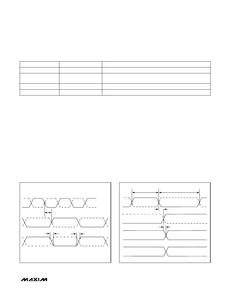
Demux Clock Generator
The demux clock generator creates the DIV1, DIV2, or
DIV4 clocks required for the different modes of demux
and non-demux operation. The TTL/CMOS control
inputs DEMUXEN and DIVSELECT control the demuxed
mode selection, as described in Table 2. The timing
diagrams in Figure 16 and Figure 17 show the output
timing and data alignment in DIV1, DIV2, and DIV4
modes, respectively.
The phase relationship between the sampling clock at
the CLK+/CLK- inputs and the data-ready clock at the
DREADY+/DREADY- outputs will be random at device
power-up. As with all divide-by-two circuits, two possi-
ble phase relationships exist between these clocks.
The difference between the phases is simply the inver-
sion of the DIV2-DREADY clock. The timing diagram in
Figure 16 shows this relationship.
Reset all MAX104 devices to a known DREADY phase
after initial power-up for applications such as interleav-
ing, where two or more MAX104 devices are used to
achieve higher effective sampling rates. This synchro-
nization is necessary to set the order of output samples
between the devices. Resetting the converters accom-
plishes this synchronization. The reset signal is used to
force the internal counter in the demux clock-generator
block to a known phase state.
MAX104
±5V, 1Gsps, 8-Bit ADC with
On-Chip 2.2GHz Track/Hold Amplifier
______________________________________________________________________________________
21
Table 6. Demux Operating and Reset Control Signal
50%
CLK+
CLK-
DREADY +
DREADY -
"PHASE 1"
"PHASE 2"
20%
20%
50%
80%
80%
t
PD1
DREADY-
DREADY+
t
RDREADY
t
FDREADY
Figure 16. CLK and DREADY Timing in Demuxed DIV2 Mode
Showing Two Possible DREADY Phases
CLK+
CLK-
DREADY +
DREADY -
AUXILIARY PORT DATA
PRIMARY PORT DATA
t
PWH
t
PWL
t
PD1
t
PD2
Figure 17. Output Timing for All Modes (DIV1, DIV2, DIV4)
Sampling clock inputs
Master ADC timing signal. The ADC samples on the rising edge of CLK+.
CLK+, CLK-
TYPE
Differential PECL outputs
Data-Ready PECL Output. Output data changes on the rising edge of
DREADY+.
DREADY+, DREADY-
Differential PECL inputs
Demux reset input signals. Resets the internal demux when asserted.
RSTIN+, RSTIN-
Differential PECL outputs
Reset outputs for resetting additional external demux devices
RSTOUT+, RSTOUT-
SIGNAL NAME
FUNCTION