2 compensating for diode non-ideality, 4 computing rpm of the fan from the tach count, Lm63 – Rainbow Electronics LM63 User Manual
Page 26
3.0 Application Notes
(Continued)
Pentium 4 processor’s thermal diode. The non-ideality factor,
η, is the only other parameter not accounted for and de-
pends on the diode that is used for measurement. Since
∆V
be
is proportional to both
η and T, the variations in η
cannot be distinguished from variations in temperature.
Since the temperature sensor does not control the non-
ideality factor, it will directly add to the inaccuracy of the
sensor.
For the Intel Pentium 4 and Mobile Pentium 4 Processor-M
processors Intel specifies a
±
0.1% variation in
η from part to
part. As an example, assume that a temperature sensor has
an accuracy specification of
±
1%˚C at room temperature of
25˚C and process used to manufacture the diode has a
non-ideality variation of
±
0.1%. The resulting accuracy will
be:
T
ACC
=
±
1˚C + (
±
0.1% of 298˚K) =
±
1.3˚C
The additional inaccuracy in the temperature measurement
caused by
η, can be eliminated if each temperature sensor is
calibrated with the remote diode that it will be paired with-
.Refer to the processor datasheet for the non-ideality factor.
3.3.2 Compensating for Diode Non-Ideality
In order to compensate for the errors introduced by non-
ideality, the temperature sensor is calibrated for a particular
processor. National Semiconductor temperature sensors are
always calibrated to the typical non-ideality of a particular
processor type.
The LM63 is calibrated for the non-ideality of the 0.13 micron
Intel Pentium 4 and Mobile Pentium 4 Processor-M proces-
sors.
When a temperature sensor, calibrated for a specific type of
processor is used with a different processor type or a given
processor type has a non-ideality that strays form the typical
value, errors are introduced.
Temperature errors associated with non-ideality may be in-
troduced in a specific temperature range of concern through
the use of the Temperature Offset Registers 11
HEX
and
12
HEX
.
The
user
is
encouraged
to
send
an
to
hardware.monitor.team
@
nsc.com to further request infor-
mation on our recommended setting of the offset register for
different processor types.
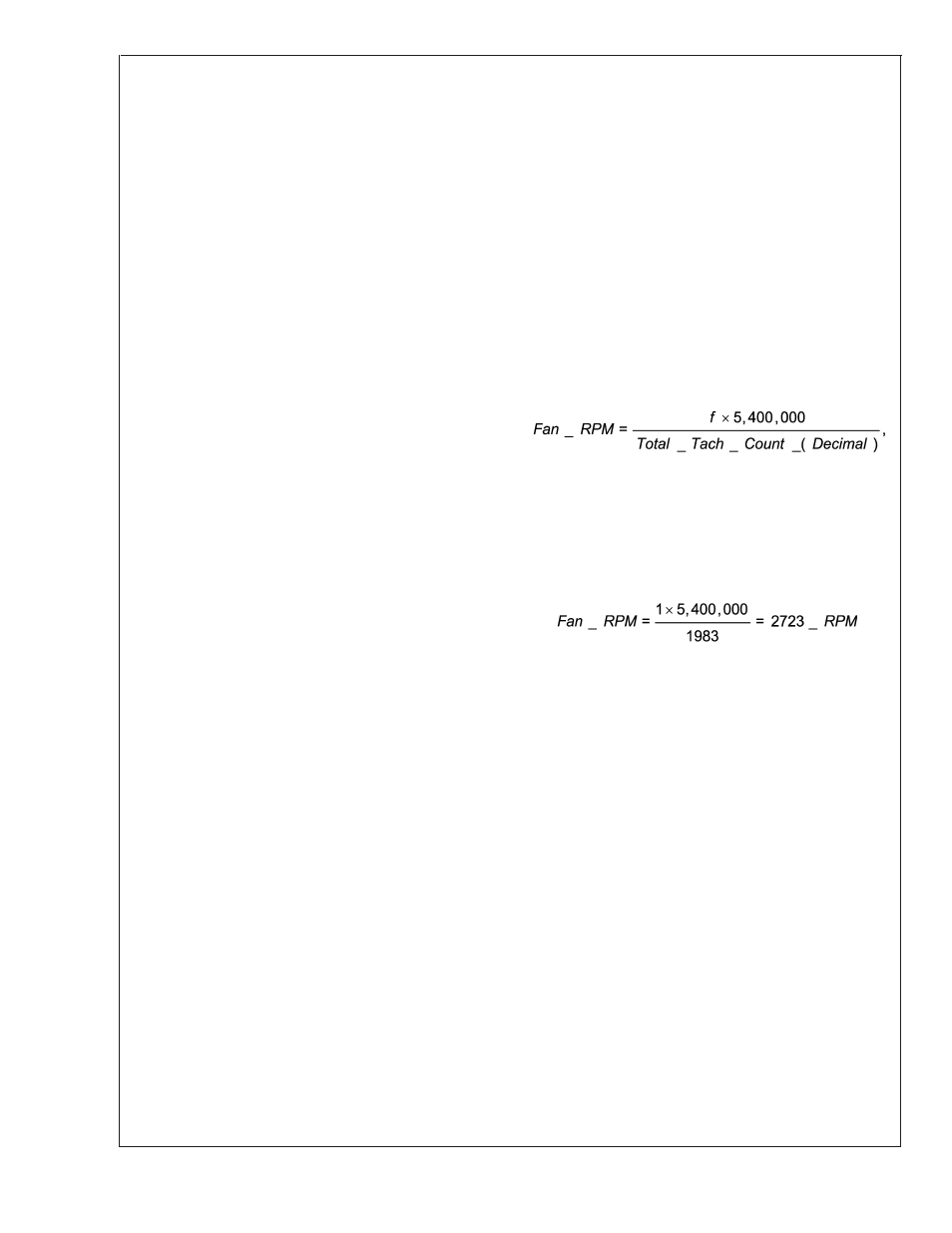
3.4 COMPUTING RPM OF THE FAN FROM THE TACH
COUNT
The Tach Count Registers 46
HEX
and 47
HEX
count the num-
ber of periods of the 90 kHz tachometer clock in the LM63 for
the tachometer input from the fan assuming a 2 pulse per
revolution fan tachometer, such as the fans supplied with the
Pentium 4 boxed processors. The RPM of the fan can be
computed from the Tach Count Registers 46
HEX
and 47
HEX
.
This can best be shown through an example.
Example:
Given: the fan used has a tachometer output with 2 per
revolution.
Let:
Register 46 (LSB) is BF
HEX
= Decimal (11 x 16) + 15 = 191
and
Register 47 (MSB) is 7
HEX
= Decimal (7 x 256) = 1792.
The total Tach Count, in decimal, is 191 + 1792 = 1983.
The RPM is computed using the formula
where
f = 1 for 2 pulses/rev fan tachometer output;
f = 2 for 1 pulse/rev fan tachometer output, and
f = 2 / 3 for 3 pulses/rev fan tachometer output
For our example
LM63
www.national.com
26